Inductor said:
Hi Andy,
I saw your stuff, good work there.
I wonder why you go for series xover when they don't allow for padding or assimetrical, maybe just some more experiences...
Nice, even so.
What do you mean, "don't allow for padding or assymetrical" ?
You can add padding to a driver any time, and you can mix say 1st and second order eg 1st on the woof 2nd on the tweeter.
You can even add other bits and pieces should you feel inclined , eg notch filters, LR BSC, etc etc.. you just have to remember that any bits you add will affect the whole filter, so once you start adding these bits and pieces, you really need to be able to model them.
So if I add attenuation to the tweeter it affects the mid or the woofer... I guess it's that that is confusing, but after learning the facts you get there.
I just found another site from Tony Gee
http://www.humblehomemadehifi.com/Crossover.html
is not my type (of xover) anyway, maybe one day.
Great wood work Andy.
I just found another site from Tony Gee
http://www.humblehomemadehifi.com/Crossover.html
is not my type (of xover) anyway, maybe one day.
Great wood work Andy.
if you just add a series resistor, it will effect the slope and x-o very slightly
if you add a proper L-pad, it won't.
if you add a proper L-pad, it won't.
Hi everyone , wow this thread is hotting up!
Andy,
Thanks for 'dropping in'! Is Saturday ok with you if its not raining (my 21yo car is hopeless in the rain!) I'll ring you Saturday morning, but if you have to go out thats fine of course! Your creative speakers are very, very well appraised by numerous people!!! And your site is amazing! In particular your series crossover section convinced me to try it, after Sreten firstly suggested that a
hybrid topology would work!
Tinitus,
I hope you don't mind me asking more questions please about the Tang Band W4-1337SA?
Re: ..."But I think the TB is very interesting with its underhung coil ... and allthough with titan it seems very well behaved with a possible big passband ... I guess its a very clean sounding driver with good
detailed sonics, but it dont take too much power, so lower xo point should not be too low. It may blend very well with any good tweeter, and perfect fore the shallow series xo you are looking at, but it may be more tricky to get the bass right"
Thank you very much for these comments. Yes the bass with the P25 looks real tricky indeed! The P25 is already 90dB at 300Hz and above, while the TB-W4 is sitting on about 86dB but needs to be crossed higher? Its probably a mismatch....unless ...(possibly?) as Sreten suggested before, change the P25's Qts (by a series resistor, I think) and CLOSE the box! Maybe a higher DCR coil would help too? I'll try to simulate it with second order (electrical) series on P25 and 1st order (not sure if series or parallel would mix here?) on TB with 10kHz+ filter.
Thanks for your tweeter comments and suggestion of D26NC55.
I haven't 'officially' changed to the bass and full-range idea just yet, but hey its got to be worth a try if the bass 'problem' can be sorted out. There could be 'method in my madness' Lol! because while it seems like a very fine driver, that is, mid-woofer/midrange and possibly tweeter too! If the treble is not to my liking, I can always make it a 3-way later! The response (to 10khz) and harmonic distortion look better than the MCA15, but the power rating is much? lower - TB say 50W max so maybe not a problem?. cheers, grant
Sreten,
Thanks for your test CD link, I'll try to pick one up!
Omni,
Thanks for your updated crossover drawing. It will be good to see the response chart. Sreten has mentioned previously that the electrical phase is important (I hope this is correct?), so it might be good to plot this? I'm well 'out of my depth' here, ... I wish I could help you, my friend! Hopefully, some of the experts in here
can help you with tweaking etc? Frankie LIVES! YAY!
Omni,
Hi again...Regarding your comment "some break in phenomenon is occurring, like a kids voice that changes as he is getting older"...I've been thinking more about this and also the sound of my previous
crossover which I would describe as a very similar symptom. I could be wrong of course, but could it be that your crossover is 'wandering'? As always please take my 'advice' very lightly!...but are your M&T
attenuation resistors properly configured and wired/soldered? best wishes, mate! grant
Grant, its only good that woofer is a few db more efficient ... BSC
The power rating of the TB will be better if used as a mid with no bass duties, and possibly gain a bit in SPL
With the recommended tweeter with a high xo point you will get very nice sound ... I have no doubt about it
If thats what you want, I would order the tweeter while its available ... its a discontinued model ... allthough JohnKrutke states that Madisound has a huge stock that will last a while
Hi,
The Test CD, I could dig it out and MP3 it .....
The bass unit and mid unit may work well with a 1st order series
c/o aligned with the baffle step of the intended cabinets, (we
have been here before regarding the 86dB/W seas 4" mid unit).
The TB may have a rising top end but off axis ?
Looks to me to be a candidate for a mechanical treble diffuser ......
Reserving commenting on "frankies" crossover until I've seen the
curves, but at first glance the amount of BSC does not look right .....
🙂/sreten.
grantnsw said:
Andy,
Thanks for 'dropping in'! Is Saturday ok with you if its not raining (my 21yo car is hopeless in the rain!) I'll ring you Saturday morning, but if you have to go out thats fine of course!
looking forward to a meeting a fellow audio addict 😀
So long as I know you are coming, I can be here.
catch Ya.
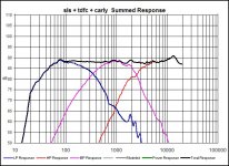
Its quite clear that there is a small problem around 2khz, on all drivers 
Fore simulation only
Try a "notch" on woofer first
Next, try 1.2-1.5ohm on midrange, instead of 1ohm
On midrange 14uF paralel, try a resistor to ground(-)
RC on tweeter
Fore perfection, maybe a "notch" on midrange
Maybe midrange series inductor(o.84mH) is too big ... a bit bigger series resistor(the last 1.2ohm) will turn it down a bit, bigger resistanse will make the inductor smaller and at the same time attenuate mids ... and maybe a resistor on the paralel 14uF
tweeter paralel inductor could be smaller with series resistor to ground
At this point it may be necessary to attenuate tweeter a bit more ... as it is a series resistor only it will change cap and inductor values a bit
Omni,
I've been re-reading Lynn Olson's original 'Ariel' crossover tweaks and some of it may be of use?
www.nutshellhifi.com/Arieltxt2.html#xt I really like his idea of using a stereo Lpad
www.partsexpress.com/pe/showdetl.cfm?&Partnumber=260-264 on 15 feet of wire! He walked around the room and adjusted the Lpad for best sound and measured the resistance. Is it possible that
both your M and T's need Lpads? I read somewhere that its desirable to do this. The tweeters would need discrete resistors? (as there are no 6 ohm Lpads, ...is this sensible or a really 'dumb' comment?)
Lynn says "since the ear is approaching its greatest sensitivity in the 2-5kHz region, even very small peaks create an unpleasant and unnatural sibilance". Its interesting that all your 3 drivers have a slight hump at about 2kHz.but the SLS peak is possibly the biggest contributor even though its nearly 30dB down! It looks like you have Zobelled the woofer?, so yes, maybe a woofer notch filter at 1900Hz could do the trick. Is the 1R in the Mid circuit an attenuator? There's a few freeware Pc based signal generators around, Speaker Workshop has one and this one too : www.download3000.com/download_2259.html
Anyway best of luck with your tweaking and measurements. OOPS, I just read Tinitus' post # 710.
Tinitus,
Yes, re BSC oops, I forgot! It could work in my favour. I'm wondering what you consider would be the lowest TB W4 crossover frequency for best power rating ? I'm trying to find the chart for relative power levels. Initially I would be considering no tweeter, because it might sound ok with some 10+kHz filtering. Zaph seems to think it could work full-range.
Sreten,
I'm sorry your previous BSC advice just slipped my mind! Oh, the TB off-axis response might not be suitable if I filter it based on 'on-axis'? I can't find any off-axis plots as yet. A 'mechanical treble diffuser'....lol. MP3'ing your test CD seems like a lot of work!
Tinitus....Grant...........I studied the summed response chart after Tinitus' comments and see that nasty spike in the woofer at 2000 Hz..............I am gonna simulate some notch or contour filters this weekend to see if I can eliminate it...........This definately could be part of the culprit..........And as you pointed out Tinitus, I like your measured approach to Frankies ailments.............There is a good explanation of notch filters and contour networks in Dickasons Book.........It shows how to figure component parts based on the frequencies that need attention......I will study this and then experiment with my simulator....If I run into any trouble, I will inquire as to alternate methods of figuring out component values............Grant, I don't know for sure about the L pads, and due to this uncertainty, I am not sure whether they would adversely affect the impedance of the system or not.I will check out the links and study them...........And by the way......no, it was not a dumb comment............If you want to hear dumb, listen to this......You see that nasty spike in the woofer at 2000Hz?......I saw it before, but did not think that it would have any relevance to the crossover or sound..............I think I was mistaken.............I will keep you all posted............Omni
Good spirit, good teamwork🙂
Yeah, I guess we all noticed the problem, but didnt know either how significant it would be, and afraid to complicate things too much ... you might have lost your senses
At least, now there is something to work with
Actually those abnormalities in the stopband is something I rate as exstremely important, but its only theoretical ... and what I think I might hear when I work with my speakers
But I remember a late mentor who claimed that the slopes should be under controll all the way down to -90db ... well, maybe this will prove it
Hi Omni,
I have some (very respectful! , of course! ) comments on your crossover and all the hard work you put into it, but (and the usual proviso...I could be wrong!) a couple of things don't seem quite right to me. I hope my comments are worthwhile to some extent.
I have just been looking at your SLS woofer 'raw trace' again and it has a 6dB peak from about 1600 to 1900Hz, so imho it will need a 2nd order parallel electrical and possibly a suitably configured Zobel to control it..
Whether 2nd-order(E) or a 'notch' or EVEN BOTH might be borne out only by simulations and listening/tweaking.
Anyway, I reckon get the woofer properly smoothed/rolled-off first! On second looks at your woofer network it doesn't seem to be Zobeled after all? It seems that you have a 'tweaking resistor' on your second order cap but no seperate Zobel as such?
I just reviewed your raw data SLS zma file and ( possibly quite rightly? ) it only goes to about 500Hz. * But *, shouldn't the zma plot 'track along' to the end of the frd plot for consistency in the program? Otherwise the FRD tools wouldn't know what the impedance is at say 2kHz where the woofer is still contributing to the response!
Onto the CA...I'm not sure why the 1 ohm resistor is there? To me it IS attenuating... so shouldn't it be added to the 1.2 ohm in that spot? A total 2.2 ohm attenuation might not need an Lpad here, just series Rs. I'd have to check that 'Lalena' site and possibly sim it. The raw CA15 Z plot looks like it could do with a Zobel as well.
Sreten and Tinitus would know this stuff!
The TDFC isn't Zobeled and imho doesn't need to be. I have looked at all 3 drivers overall 'raw-in-box' response plots, and the TDFC is sitting on about 90dB, the CA15's IN BOX response has that dreaded peak/dip...about 90dB at 700Hz down to about 82dB at about 1800?Hz which combined with the woofers peak at about the same frequency is partly (secondarily to 'xo wandering') causing you problems. The Peerless final response of an in-box 6dB rise at 1900
together with the CA15's dip of 8dB from 700 to 1800 is a problem but fixable! .....Yay, good news!!!!
The perceived ( by me ) 'wobbling xo-point' seems fairly straightforward too, well to me at least. This would certainly explain
Frankie's 'voice-change'! So mate, I think no 'dramas', just a couple of things to address and hopefully Frankie will sing beautifully!!!
Regarding the dreaded peak/dip in the CA15's 'in box' response, due to BStep/diffraction.... the filter I suggested many 'pages' ago,
umm, maybe its worth a try? It does seem very effective. More parts count though.
Omni, I'm sorry to 'rant on' so much, its just that I want to help you as much as I can (with my limited knowledge)...but I really am sure the Lpad technique is good as far as Lynn's tweaking of series resistors on shunt parts and of course very much so on test Lpads too! I'm showing my age but my copy of David B. Weems "Designing, building , testing etc Speakers 2nd Edition, get this haha...1964! page 125 has 8ohm Lpads on both mids and tweeters. It just goes to show that I haven't learnt much, or I've got 'old-timers' disease! hehe , very best wishes with Frankie!...grant
( I'll post an update on my visit to Andy_G's today, soon....Thanks Andy! Your speakers are awesome! )
My post # 716.... well it made a lot of sense when I wrote it! haha
Tinitus, I think you are correct! in your last post. And you have very wise thoughts.
Tinitus, I think you are correct! in your last post. And you have very wise thoughts.
Well, thank you ... I think this is a matter of "keeping a steady hand" and find solutions, so that Omni dont have to make too much changes ... you can always make an inductor smaller, and the series resistors could be changed with effect on the slopes too ... "notches" are easily applied and so on
This only a matter of some minor tweeking, and only to be exspected, but not to say that its easy though
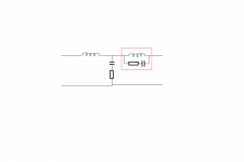
Again, this is how I have done my bass lowpass ... the part framed in red really makes wonders ... looks a bit like a bypassed 18db with adjustable attenuation on the paralel C and last inductor ... ofcourse it will have some effect on phase, and on my speakers its only positive
This only a matter of some minor tweeking, and only to be exspected, but not to say that its easy though
Again, this is how I have done my bass lowpass ... the part framed in red really makes wonders ... looks a bit like a bypassed 18db with adjustable attenuation on the paralel C and last inductor ... ofcourse it will have some effect on phase, and on my speakers its only positive
Attachments

Grant..........A lot of the issues you brought up are definately thoughts that I have entertained during the simulating phase in Bagbys simulator...........You are correct: that is not a zobel on the woofer and it is indeed a tweaking resistor on the shunt cap as per Tinitus' suggestion to experiment with series resistors on parallel components..........What this did was smooth the rolloff characteristics of the woofer without adversely affecting the overall response..........It did wonders to make the rolloff more rounded and create a smoother scenario at the crossover point.........As you probably recall our trepidation pertaining to a zobel on the woofer based on the concern that impedance may be lowered too much, thus causing an excessive, and possibly damaging strain on the amplifier...........I will have to review my woofer zma raw data..........That 1 ohm resistor you mention, and its' placement was strange to me too.........However, after multitudes of simulations, placing resistors in differing locations, this was the topology that rendered the smoothest summed response.........I studied a lot of writings on crossover topology, and found that differing topologies with the same components can render differing responses......Bagby, in his correspondance to me, suggested that I be open to all different kinds of possibilities when working with the simulator, and that some amazing results can be achieved with some bizarre component combinations.............As to the placement of that 1 ohm resistor, my { uneducated } guess is this: It probably affects the midrange signal from that point on..........having an effect on the characteristics of the rest of the crossover, because it comes so early in the topology....This was the topology that provided the smoothest overall response, so I kept it there...........That pesky little dip..............Man, this is what we have been battling with from the start.............The amazing thing is this: I am encouraged by the fact that even though Frankies' sound isn't quite spot on yet, he does sound very good as he is, without any response shaping circuitry.............Had I had the foresight and knowledge earlier in the process, that I have subsequently gained, and put it into use designing Frankie, things might sound different..........However............I am not discouraged, by the fact that you guys are here, keeping me on my toes and providing insight on how to deal with it..........Van Gogh is known for his thick impasto painting techniques..............I bet there are plenty of mistakes buried underneath his heavy top layers..........I am going have to search for the filter you suggested, but if I can't find it can you tell me what page it is on? I am open to all the possibilities...........Tinitus, is that a parallel trap filter you show here, situated on the woofer leg, and how did you determine component values..........I have not gotten back on the simulator yet, but the weekend has just begun...I have got a little research left to do yet, but from there, it's on to the simulator.........I will report my findings, probably tonite.......................Omni
Tinitus..........I did some initial research on the notch filter in Dickasons' book and attempted his calculations, then inserted the results into my simulator, but got no tangible results............So I did a search on this furum and found a FEW threads addressing the subject, but again no actual methodology as to how to get a reference starting point for component values...........I will do a web search to try to find the information................In the meantime, I created a new thread here on the forums, and also included Frankies' response graph in the hope that more people will see the problem Frankie faces, and offer up their expertise..........Hopefully the graph will provide readers with some concrete data from which to draw............Another thing I did do with the simulator, was throw caution to the wind and started simulating with far out numbers, and got some movement on the graph, but it required me to change the series resistor on the shunt capacitor to 7 ohms.............However, the problem here was that this change really took the woofer impedance graph way out of whack...............Not like anything I have ever seen before...A bit scary................How would you think that I proceed?........The other changes you mentioned in an earlier post don't seem to be daunting, and I think they will be able to be accomplished without too much difficulty, judging that the other anomolies don't appear to be as radical as those spikes in the woofer stopband...........But I definately agree with you that the woofer problem must be addressed, and it seems to me that the wise thing to do here is to address it first, before making any other changes.......Do you agree?............................cheers and hopes...................Omni
- Status
- Not open for further replies.
- Home
- Loudspeakers
- Multi-Way
- 3way XO help greatly appreciated!