Hi Bill,
So this morning I ordered the four celestion mids, meaning I finally have all the drivers for a stereo pair of this project. Thanks for developing a passive network - that’s how I’ll be running this. Conveniently, I also have a pair of 10AWG 3.5mH air core inductors left over from a different Bwaslo build.
I have a Folgertech R2 still in its shipping box. I don’t currently have a place to set it up and don’t really have a need to outside of this project.
Did you move the mids down 25% like you mentioned a few months back? Or did that turn into the 3D stub project? Hopefully Portland’s rainy season hasn’t dampened your spirits on this project. Okay bad pun.
10AWG Air core 3.5mH? Must be HUGE!
I'd start building the FT-5 early, it's not a quick build (and there have been issues with missing parts sometimes).
I don't remember wanting to move the mids 25% down (?). I do think if I were to make another set, I'd move the WOOFERS' ports about 25% further out from center to tweak the way they extend the horizontal directivity. That would put them on the edge or just on the outside of the horn, so the easiest thing to do would be to remove the woofer mounts from the horn itself and mount them (woofers mounted inside, with cones pointing toward the sides) and provide slots in the cabinet for them to exit through. Slightly more difficult cabinet to make, but easier 3D print to make. Would need the model modified to take the woofer stuff off, though, which could get involved.
Yes, the Solen inductors are big. My preference for aircore inductors is one of those audiophool biases I’ve found hardest to shake.
I probably misunderstood the following, from post #28:
I was reviewing your Small Syns design and noticed it’s impedance is much more flat than the printed horn crossover, despite using the same mid drivers. Is this due to the difference in woofer placement?
I don't remember wanting to move the mids 25% down (?). I do think if I were to make another set, I'd move the WOOFERS' ports about 25% further out from center to tweak the way they extend the horizontal directivity.
I probably misunderstood the following, from post #28:
Edit again: Got myself confused here... it looks like the woofer ports should move **outward** a few inches, not inward, and then the mid crossover should be moved down about 25%.... I think. That would put the ports on the edge of the horn. Maybe vertical slits on the cabinet (or in those angled sides) for the woofers?
I was reviewing your Small Syns design and noticed it’s impedance is much more flat than the printed horn crossover, despite using the same mid drivers. Is this due to the difference in woofer placement?
Yes, the Solen inductors are big. My preference for aircore inductors is one of those audiophool biases I’ve found hardest to shake.
No, air core is definitely preferable if the series resistance is kept down, and if you can afford it (and have a place to put it). Just that the inductor sounds like you could sell it for its copper weight and buy entire speakers from that 🙂
I was reviewing your Small Syns design and noticed it’s impedance is much more flat than the printed horn crossover, despite using the same mid drivers. Is this due to the difference in woofer placement?
placement shouldn't make much difference. I sometimes add a flattening network (resistor and capacitor) across the crossovers to flatten impedances at higher frequencies (in case someone decides to use them with a tube amp at some point). Not sure which curves you're looking at or which crossover components were involved though. The Small Syns crossover is different from the printed horn crossover (which uses two midranges instead of one)
Ah, that's the sealed cabinet (first, smallest) version. The later one was a ported cabinet, as is the largest printed waveguide speaker.
Interesting.
The printed horn looks just over a foot tall. If someone were to run it sealed like your first Small Syns iteration, how much clearance is required above and below the horn? In other words, what do you think is a realistic estimate for the height of a sealed cabinet?
I’m thinking of passively crossing over to a 15” midbass module around 250Hz or so that’s about 30 inches tall.
I’m thinking of passively crossing over to a 15” midbass module around 250Hz or so that’s about 30 inches tall.
You know a man is serious about his audio when he says things like "fifteen inch midbass"

Lol John, I’m blushing.
It’s partly because I’d rather have a “stand” for the horn that also sidesteps the floorbounce issue.
The DIYSG makes it so easy. The 12” MBM is a 93dB unit, the 15” MBM is 6 ohm and 99dB. I like that kinda future proofing and the width of the printed horn allows for it.
But yes, monstrous.
It’s partly because I’d rather have a “stand” for the horn that also sidesteps the floorbounce issue.
The DIYSG makes it so easy. The 12” MBM is a 93dB unit, the 15” MBM is 6 ohm and 99dB. I like that kinda future proofing and the width of the printed horn allows for it.
But yes, monstrous.
Last edited:
Hi Bill,
I noticed you used Fusion360 to design these. I've used Fusion360 for all my projects and tried designing a synergy horn in Fusion360 without success. I built a male model (inside shape of horn and then tried to subtract it from a solid to create the female horn shape. But it won't subtract. Do you have any tips you can share on how you designed these in Fusion360? BTW, 99% of my design was in parametric modeling mode. I'm really curious how you blended an oblique spheroid with the final shape. I've built really complex assemblies in Fusion360, including a kitchen remodel, but the horns I'm struggling with.
Also, did you ever start a thread on the Behemoth synergy?
...I'm really curious how you blended an oblique spheroid with the final shape. I've built really complex assemblies in Fusion360, including a kitchen remodel, but the horns I'm struggling with.
I made a table of x/y points in a spreadsheet defining the curves (oblate spheroid, ending in a large radius for the horizontal and vertical angles). Imported them into spline curves in Fusion360. Then put a 1"dia circle where the throat was, a rounded rectangle where the end of the mouth was, attached the spline curves between them at the proper points. And did a "loft along rails" between the circle and rounded rectangle. That part took the longest to get working, mostly because I wasn't clear the on how Fusion360 considered sketches and their planes - I spent a long time with lots of questions in forums about getting F360 to agree that two points that were on the same coordinates were actually touching each other! 😱
Then, for thickness, I used a tool in the 'sculpt' section, though don't offhand remember what it was (but wasn't hard to figure out). And just thickened the horn shape. For a Synergy, since there needed to be drivers on the back, I didn't want something subtracted from a block, but something with enough thickness that a mounting surface could be added onto the back side of.
Also, did you ever start a thread on the Behemoth synergy?
You mean the one using plywood and horn 'stub's for mounting the mids and tweeters? No, I kind of abandoned that project. Not because I don't think it was worth it or that it wouldn't work out, but because I looked at the space I had and there is literally nowhere upstairs or downstairs here to install horns like that, and not really any place I could even store them except maybe out in the back of the already crowded garage. So the finished printed stubs sit on a shelf. Maybe someday if I find a community theater that needs speakers or something like that I might do it, but for now it would just be a lot of work that would only generate problems for me afterward. 🙁
That is helpful! I understand your approach as I have used the spline/loft method numerous times. And I have also had the same problem with F360 not thinking points are touching! I'll have to search for the threads in which you discuss it - I may pick up some tips. I'm glad this route worked for you because I was thinking maybe you were using T-Splines or equations to create the shapes. Thank-you for the overview!
When I subtracted the male model from the positive, it wouldn't accept it as a whole body so the horn had objects in it. I could have 3d printed and cut them out, but I would rather learn the software first. I'll try your approach (although I did use loft for part of it).
Yes, those Behemoths! No worries, I was just curios and was going to follow the thread if there was one. Now back to modeling and studying synergy horns...
That part took the longest to get working, mostly because I wasn't clear the on how Fusion360 considered sketches and their planes - I spent a long time with lots of questions in forums about getting F360 to agree that two points that were on the same coordinates were actually touching each other! (
Bill, can you share some advice on this? I'm having exactly this issue using an ellipse as the profile to a waveguide wall. I can't select them as rails because they are not connected to the mouth and throat profiles.
FYI: you can make an elliptical oblate spheroidal waveguide in 123D in less than 20 minutes:
3D Modeling Tips and Tricks
I tried Fusion 360 but everything takes so much more work to accomplish. Rhino is nice too. Blender is too obtuse imho.
3D Modeling Tips and Tricks
I tried Fusion 360 but everything takes so much more work to accomplish. Rhino is nice too. Blender is too obtuse imho.
Hi Brandon,
If you have a shape on a plane and you want to attach it to something like a rail that isn't on that plane and have F360 see it as attached, you have to look at not just the plane but at the sketch that the shape was made on. You need to project the points from the rail onto that sketch. The goal is to project the attaching point from your rail (onto the same 3D coordinate that it's already at!!) -- but one that is on the sketch where the shape is. (The other points from the rail get projected along with it onto the sketch's plane, but you can ignore those). Having a point projected onto the sketch allows F360 see and deal with that point when it is doing anything having to do with that sketch. A different sketch, even if it's on the same plane won't do. If I remember correctly, that means the rails have to be created in a step previous to the one for the sketches that have the throat and mouth shapes (so you can get to them when in Edit Sketch, where you need to do the projecting from). There might be a way to do it in a different order, but I'm not sure about that.
If you have a shape on a plane and you want to attach it to something like a rail that isn't on that plane and have F360 see it as attached, you have to look at not just the plane but at the sketch that the shape was made on. You need to project the points from the rail onto that sketch. The goal is to project the attaching point from your rail (onto the same 3D coordinate that it's already at!!) -- but one that is on the sketch where the shape is. (The other points from the rail get projected along with it onto the sketch's plane, but you can ignore those). Having a point projected onto the sketch allows F360 see and deal with that point when it is doing anything having to do with that sketch. A different sketch, even if it's on the same plane won't do. If I remember correctly, that means the rails have to be created in a step previous to the one for the sketches that have the throat and mouth shapes (so you can get to them when in Edit Sketch, where you need to do the projecting from). There might be a way to do it in a different order, but I'm not sure about that.
FYI: you can make an elliptical oblate spheroidal waveguide in 123D in less than 20 minutes:
3D Modeling Tips and Tricks
I tried Fusion 360 but everything takes so much more work to accomplish. Rhino is nice too. Blender is too obtuse imho.
Thanks for linking your thread! Good stuff. Unfortunately, Autodesk dropped 123D a year or so ago. There is a Windows version download still out there, but my preference is to learn current software (and stay Mac when possible). I'll try Bill's approach in Fusion360.
I hear ya'
I'm always so wary to learn new software. I used Bandpass Boxmodel for about ten years after DOS was no longer published, and I still do all my 2D work in Xara
I'm always so wary to learn new software. I used Bandpass Boxmodel for about ten years after DOS was no longer published, and I still do all my 2D work in Xara
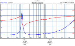
I got around to testing my four Celestion closed-back mids (TF0410MR) I picked up for this project. I'm using DATS v2 and deriving Vas using the added mass method.
3 of the 4 mids spec within tolerance of each other. One of the four looks to be the odd man out, with about half the magnitude Z at f(s), lower BL, 3dB lower SPL and about double the Q(es) vs the others.
I've repeated the test several times and the results are consistent. I retested the other three drivers as a sanity check and they were consistent as well.
I expect I want all four drivers to measure as close as possible to each other as I plan on using the passive crossover. 3dB seems like a big difference. Should I replace it?
Yeah, I'd replace it. I had one dud out of about a dozen of those drivers, too (about 3dB less SPL).
Thanks Bill
I just finished testing the woofers (6FE100) and all four look good.
A very kind member of the forum PM'ed me within minutes of my last post offering up a pair of leftover Celestions from their stash of goods. So I'm pretty lucky, actually.
Our place isn't very big but I just got a corner desk in the bedroom we converted into an office a while back. I think I might have enough room on the desk to setup the printer, now that I found a way to make having a 3D printer an asset for my job. Much harder sell than when it was just for the hobby.
- Home
- Loudspeakers
- Multi-Way
- 3D printed 3-way Unity waveguide home audio speaker