Whether a fan is needed has a lot to do with the specifics of heatsink surface area, exposure to outside air, size/number and location of vent holes or slits, etc.
Transformers are rated for output current @ temperature without consideration of any 'sinking away of heat (unless specifically stated otherwise), but likewise that is with a chassis able to keep heat buildup below a certain level. I would plan it out and space components so you can add a lot of vent holes or slits if necessary then test the amp to decide if you need to add them all.
Adding a fan is easier, but I try to avoid doing so if possible. Even so, a very low RPM fan moving very little air will still make a big difference in chassis temperature. If you add one, don't run it direct on the amp power rails, they produce a fair amount of electrical noise.
I doubt it would get hot enough to warp the acrylic, both because you are using thick acrylic and because having pieces cut to shape there is no stress on the acrylic, but I must admit I have never heat cycled acrylic trying to see if it would warp in a range you might have in a poorly cooled amp case. Generally heat buildup will kill electrolytic capacitors sooner than anything else.
... and if you think you may need a fan, leave space on a panel so it can be added later IF needed.
Click on "File", then "Export" then "2D Graphic model".
Make sure you set up your view first, what you see on the screen is what will be printed.
As long as the Acrylic is not too thin or over spanned, it should OK to use, depending on how you use it.
Make sure you set up your view first, what you see on the screen is what will be printed.
As long as the Acrylic is not too thin or over spanned, it should OK to use, depending on how you use it.
!----- The entire chassis is actually the heatsink and nothing will be mounted to the acrylic. What bothers me is that the spiked feet hold the bottom piece of acrylic on and they are around 8" apart. i do have a smaller 1 1/2" fan somewhere in a box of stuff. I might have to dig it out and see what the voltage rating is on it. I might use 2, make one push and the other pull if I have too. I would much rather overkill the cooling inside the case and try to keep the noise down as much as possible...... I'll have to set it all up and run a fan to see if I get any unwanted noise first.
Globug------ Thanks for the help! I'll have to do it when I get home tonight so that maybe I can get the "bugs" worked out before I go any farther.
Globug------ Thanks for the help! I'll have to do it when I get home tonight so that maybe I can get the "bugs" worked out before I go any farther.
No problems.
Consider using a bigger fan at lower speed/voltage if the 1 1/2" is not quiet enough for ya.
Consider using a bigger fan at lower speed/voltage if the 1 1/2" is not quiet enough for ya.

I would wonder if it's going to work out well with the chassis as the heatsink because that will expand the metal (and contract it when cooled), so you may need to leave a bit of a gap between the metal and plexi and have some play in the attachment points rather than tight ones. I may be wrong, never having built something with these factors before.
Well..... I think I'm going to run with it bolted tightly together for now and see if it moves any. If the acrylic does decide to warp or move I have a couple 12"x18" sheets set aside.Kind of a trial and error
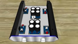
OK here's a quick shot of what I'm looking to do for adding another kit for a subwoofer.
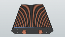
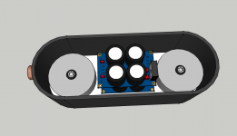
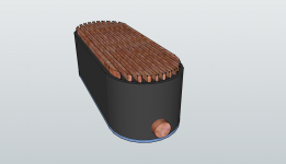
The first shot is upside down with the acrylic sheet removed and the second shot is of the topside with a view of the selector and the volume knobs.The third shot is the actual case.
Hope this comes out OK and helps visually
The first shot is upside down with the acrylic sheet removed and the second shot is of the topside with a view of the selector and the volume knobs.The third shot is the actual case.
Hope this comes out OK and helps visually
Attachments

Last edited:
That's looking real good so far. I wouldn't be too concerned about the heat and the case/HS expanding much. You'd have to have this thing cranked fairly high (and loud) constantly to generate the kind of heat that would stress the acrylic! There is a lot of surface area with that case to dissipate the heat. Now, if it was using Darlington output devices in TO-3 cases that's another story. 😀 Looks great.OK here's a quick shot of what I'm looking to do for adding another kit for a subwoofer.
The first shot is upside down with the acrylic sheet removed and the second shot is of the topside with a view of the selector and the volume knobs.The third shot is the actual case.
Hope this comes out OK and helps visually
redjr----Thanks for the encouragement! This started out being a quick,simple and cheap means of entertainment. A sort of "let's see if I can do it" kind of thing. Now it's turned into it's own monster. I'm still working out the kinks and ordering better parts one piece at a time.
I was able to find a 1 1/2" fan from an old car CD player. It's a 12v 0.10amp 2 wire fan. I've put it on a battery and it works, surprisingly quiet too!
I've also noticed that I'm getting a TON of advise from this forum........a lot more than anywhere else I've tried. Thanks guys!
I was able to find a 1 1/2" fan from an old car CD player. It's a 12v 0.10amp 2 wire fan. I've put it on a battery and it works, surprisingly quiet too!
I've also noticed that I'm getting a TON of advise from this forum........a lot more than anywhere else I've tried. Thanks guys!
You can use two toriods or one, (or even three if you want one for every channel), but the fewer you use, the higher VA rated each should be to have max output capability. Using only one I'd go with at least 300VA and lean towards 400VA.
Some people would opt to use more than one for greater channel power separation but the effects are reduced enough that I personally wouldn't bother if you have ample capacitance (4700uF or higher per rail, x2 when adding sub amp so ~ 10,000 uF total or more).
The other consideration is you might want a 2nd transformer to use lower voltage for the bridged sub config.
So if I do decide to go with a second kit for a bridged subwoofer would 2 antek AN-2222 be about right with 4ohm speakers?? or would it be better to get two more amp boards and build my own power supply?
If so I thought about something like this....
Attachments
Last edited:
You have not mentioned impedance of the sub. Lower impedance makes lower voltage more optimal, as does bridged config. One thing we can assume is that if your primary speakers are 8 ohm but your sub isn't, then the best voltage using a bridged config for the sub would mean using a lower voltage transformer for it than your L/R amp voltage.
I hate to bow out of the topic but personal issues require me to do so, others will provide more info.
I hate to bow out of the topic but personal issues require me to do so, others will provide more info.
ok. well thank you for all of your input and advise. You have helped me a great deal!
The subwoofer being used is a 12" svc 4ohm. 300w rms 600w peak with a FR Res. of 29-150 HZ
The subwoofer being used is a 12" svc 4ohm. 300w rms 600w peak with a FR Res. of 29-150 HZ
Last edited:
So am I wrong for wanting to use another kit bridged for a subwoofer or should I use a different, more powerful chip? If so, which one?
Fabricated.....
I've been following your thread with interest. I'm a little concerned you might be "overkilling" this build. The LM3886 is relatively forgiving, and keeping it simple goes along with the chipamp philosophy.
My LM3886 build is at: http://www.diyaudio.com/forums/chip-amps/201326-my-lm3886-build-thread.html
No need for a separate power supply (or worse yet, a transfomer in a poorly ventilated box, along with a wall wart). My toroid is close to the Chipamp boards I used, and if you keep your PSU wiring tight and neat, you will not have hum/noise/rf probelms).
My heatsinks are way overkill. The LM3886's never get warm enough to warrant this amount of cooling (I had the heatsink left over from a Class A project). Smaller heatsinks will be sufficient.
I have two VU LED meters that I power off the PSU rails. Rail voltage is reduced via a dropping resistor and regulator, with the regulator tied to one of the heatsinks (although the regulators only get slightly warm). Again, no need for a separate LED wall wart supply. If you are concerned about the "load" of multiple LEDs on one rail, then split the LEDs into two banks, and power each bank through it's different PSU rails (to balance the load).
Keep it simple. Keep it easy. Last thing I'd recommend: you seem to have good access to aluminum and other metals. Consider building your own amp chassis from scratch. In a lot of cases, a good high-quality chassis/cabinet is the toughest part of an audio DIY build.
Keep pressing..... the best way to learn is through doing. Ergo, DIY....!!
CanAm Man---- Thank you for your insight and interest inmy project.I am working on my final update and expectations. I have scraped the wal wart and plastic housing idea. My latest rendention for the power supply is all steel.
I have been digging at various other sites for the led information and decided to leave this thread for audio information only (pretty much just want to focus on the amp itself).
I believe I have found my ideal multiway setup... once I get it all sorted out I will have to post up what I want to power and go from there. I understand I should have posted this info at the beggining but, this whole project has been bouncing from one idea to another in my head.
Again.....sorry for running around in circles on this build but, I beleive I've found what I want to do. I'll have the specs up soon.
Thank you for your interest and I'll be following your build in the meantime
ok here we go......
total of 8 speakers in the towers. three woofers and one tweeter per tower.
woofers--6" 8ohm 50w rms/100w max FR resp. 55-5,500 hz
tweeters-- 1/2" 8ohm 30w rms/45w max FR resp. 4,000-19,000 hz
subwoofers-- 12" 4ohm SVC 300w rms/600w max FR resp 29-150hz
Now I just have to figure out where to go from here
OH YEAH!  almost forgot........ I need to stop biting off more than I can chew!
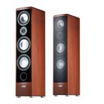
This is similar to what I'm going to shoot for...
almost forgot........ I need to stop biting off more than I can chew!This is similar to what I'm going to shoot for...
Attachments
Last edited:
fabricated,
If you are going to do DIY speakers that large, please consider the "Sunflowers" designed by Paul Carmody as an option. Iv'e been building/buying speakers since the 60s and these are the best I have owned. There are two versions of the crossover - one with adjustable mid response to match room dynamics - one with enhanced stage width and depth.
It requires only intermediate woodworking skills and the components are a great combination of quality and value. The highs are shimmering and those pipe organ pedal notes will shake your whole house with clean controlled power.
https://sites.google.com/site/undefinition/diy-sunflowers
Last edited:
- Status
- Not open for further replies.
- Home
- Amplifiers
- Chip Amps
- 3886 Ebay kit Build