Well I am addicted to using flux, so maybe that accounts for my results too, to help spread the heat and wet the solder joint as I seldom have insulation issues except with whatever type of plastic it is on common ethernet cable, that stuff shrinks quite a bit but I rarely encounter it on any other type of wire and part of the problem with the ethernet cable may be the relatively low mass of the wire itself compared to whatever it's being soldered to.
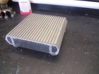
All trimmed up and ready for components
Anyone know the overall dimensions of these?? I can't seem to find them
Neutrik NF2D-B-9 RCA Jack D-Series White/Black 092-239
Anyone know the overall dimensions of these?? I can't seem to find them
Neutrik NF2D-B-9 RCA Jack D-Series White/Black 092-239
Attachments
^ dimensions are in the PDF drawing & product guide linked on the right side of their product page,
NF2D-B-9 - Neutrik
looks like you need a 1" hole saw for a clean cut mounting hole, fortunately that's a really common size since it's also used for cutting door knob cylinder holes. Even better a 24mm saw but not as common.
NF2D-B-9 - Neutrik
looks like you need a 1" hole saw for a clean cut mounting hole, fortunately that's a really common size since it's also used for cutting door knob cylinder holes. Even better a 24mm saw but not as common.
Last edited:
Hmm, I wrote 24mm isn't as common still thinking in the pre-internet era... Amazon and others have them or 15/16" for about 6 bucks, though some have awfully big teeth for cutting plexi.
well i have some fine tooth hole saws up to 4 inch. I might use a hole saw one size smaller and then follow up with a 1 inch reamer. Dunno yet
Still waiting on my new soldering iron and solder so I can practice. Still have to rework the solder on the amp boards first
Still waiting on my new soldering iron and solder so I can practice. Still have to rework the solder on the amp boards first
one piece bent acrylic won't work the bends aren't tightly folded.
going back to a 4 piece setup.....delay,delay,delay
going back to a 4 piece setup.....delay,delay,delay
meanwhile.......... with a little bit of flux and a whole lot of luck I was able to reflow my solderwork on my boards
I decided to stick with what I have now..... I was told to finish this project before I move on to the surround speakers so I'll just use what I have and "upgrade" my transformer later 😛
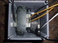
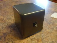
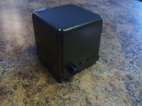
I believe I have come up with a rather unique idea for the housing. It's a 4x4x4 plastic box found in the wire isle of my local Home Depot. All of $8.00. I dug through my box of goodies and found a wall wart, cut the prongs off and soldered on a set of wire leads. It's hot glued to the the top inside of the box while the main trans. is going to be bolted to the bottom lid. Don't worry, even though it doesn't look like it, there is plenty of room around everything to be properly insulated from each other. Oh yeah...... the wall wart is going to power up the LED's in each case.....
Stay tuned......Going to be doing some copper leafing next
Attachments
Last edited:
I hate to be less than enthusiastic but I see a few problems or issues.
1) Wall wart does what? Just for LEDs? No need, they will be fine running off main amp power rail with a resistor in series limiting current. Constant current LEDs (via resistor instead of a regulating switching driver circuit) won't even add any noise to the power rail like a fan or other active electronics could. If as I mentioned below you're putting the PSU board in a separate (amp) case, you could just use a single diode and resistor for the LED in the transformer case. It'd have a little bit of 60Hz mains pulsing output (or doubled 120Hz if you used more diodes) but I doubt it'll be undesirable for a power indicator.
2) Where's the ventilation? I don't think the 3 small holes near the bottom (heat rises) are going to be sufficient, especially when using an arguably undersized transformer for the amp. Doubly so when the transformer is encased in metal itself so it runs even hotter, BUT it is possible they derated the current capability of the transformer a bit due to it being encased.
3) Hot glue + gravity + heat... think I'd find another way or as mentioned in #1, leave out the wall wart.
I'd be sure to measure temperature after powering the amp at reasonable volume for awhile. Even if it doesn't overheat a lot, large swings in temperature tend to wear out the transformer's embedded thermal fuse sooner.
Assuming you are going to put some kind of feet on the bottom so what it's sitting on doesn't block them, what I'd do is drill a bunch of vent holes into the bottom/lid of the box and a row of them on the back at the very top near the corner... and of course make sure anything inside is not blocking too many of those holes.
I'm a bit confused though, your power circuit for rectification and smoothing caps is going in the amp case or this case? Not that it necessarily matters but it does make the two boxes a bit less modular, thus most people would keep the power circuit board with the transformer.
Last edited:
Well the whole reason for the wall wart was to separate the LED's from the main trans. for "noise" issues. I plan on running quite a few LEDs in this project....up to 16. Maybe I'm being a little paranoid about it.
If that's the issue I'll remove the wall wart and put the PCB in the case with the main trans. The holes in the back are for the umbilical cords to power the main case. I haven't cut the heat vents yet. Man I'm glad I'm getting help with this!!
Like I said. I'm just trying to use what I have for now
Things that don't create a magnetic field, or radiate RF, or switch power levels don't create noise. If you were using 3W LEDs and a *proper* LED switching driver circuit that'd create a little HF noise but resistor current limiting won't.
Too great a load causing power rail droop might be a factor in some situations but in this case assuming ~ 20mA LEDs, it's only 300mA. On second thought since the transformer is already undersized I think I'd run the LEDs off +/- power rails instead of only +/gnd which is what I'd do instead if the transformer were higher current.
One other factor which will matter later is if you set a current for the LEDs with this transformer then come back later and use a different transformer, you might have a current increase to the LEDs. For this reason I'd set the LED drive current for a safe range with a future transformer's anticipated voltage and let the LEDs be a bit dimmer with the present transformer.
Last edited:
Ahhhh I see. I understand what you're saying now. I was a little confused on RF interaction issues. This would all be a little bit easier if I had a little bit bigger case and could fit everything inside. I just really like the look of what I have and really want to make it work. The next one I build will be made from scratch and large enough to accommodate everything into one package.
My whole thing is to have something completely unique. Don't get me wrong, I really like the amplifiers I have seen on this site and others as they are all of professional quality and style. I'm just trying to think outside of the box a little
My whole thing is to have something completely unique. Don't get me wrong, I really like the amplifiers I have seen on this site and others as they are all of professional quality and style. I'm just trying to think outside of the box a little
Well, after rearranging everything and relocating the power supply board to the remote switch housing I have a TON of room in the main case. So much in fact I could add another channel for a subwoofer.
If I go ahead and get the twin secondary toroid....would I be able to run another one of these kits bridged for a subwoofer off of it or would I need another toroid?
If you haven't noticed yet I am a very indecisive person that takes FOREVER to get a project finished lol
If I go ahead and get the twin secondary toroid....would I be able to run another one of these kits bridged for a subwoofer off of it or would I need another toroid?
If you haven't noticed yet I am a very indecisive person that takes FOREVER to get a project finished lol
You can use two toriods or one, (or even three if you want one for every channel), but the fewer you use, the higher VA rated each should be to have max output capability. Using only one I'd go with at least 300VA and lean towards 400VA.
Some people would opt to use more than one for greater channel power separation but the effects are reduced enough that I personally wouldn't bother if you have ample capacitance (4700uF or higher per rail, x2 when adding sub amp so ~ 10,000 uF total or more).
Also depends a bit on desired dimensions of the chassis. If it can be 1/2" or more taller it's a lot easier to make room for one larger toroid than two or three. 200VA Antek is 2.3" tall vs 2.7" for the 400VA version.
The other consideration is you might want a 2nd transformer to use lower voltage for the bridged sub config.
Last edited:
So from what I gather...... the Antek AN-3225 would be the one to shoot for. Most of the speakers I am looking to use are all 8 ohm.
Antek - AN-3225
Antek - AN-3225
I got some parts for my newest build on the way. They have to come from China, so I guess I can sit back and wait a couple of weeks! 😉 I now need to explorer enclosures and cases.
Does anyone have a list of suppliers of enclosures they have used in the past, that has a good selection and broad variety. I know Mouser has quite few, but there may also be some smaller, less known vendors too that I'm not aware of. Who's had success with vendors of nice looking cases at reasonable prices? Names? Thx in advance.
I found this one linked from the Antek site...
Par-Metal
Mike
Hey Mike. Thanks for the link. I'm going to have to think bigger, way bigger for my amp project. I receive the toroidal xformer yesterday, and it's a beast. Weighing in a around 9-lbs, and almost 4" high, I'll need a substantial case just to mount it securely! I guess I won't have to worry about not having enough current on my 65v rails. 🙂 I have seen Par-Metal, but haven't investigated them too much yet.
Edit: I'm also looking at these here.
Last edited:
I'm not sure a plastic box can house a power amplifier or a power supply, as both dissipate heat and need proper sinking.
To do proper sinking you need another surface that will also dissipate the heat: a ribbed heatsink on the amplifer and a metal sheet on the transformer.
To work the box should have to be large and have ventilation holes, already there or made by you. Heatsinks should have to be warm to touch, or you will have to force ventilation with a fan.
Wall warts may be nice for preamplifiers, but they can't provide the current you will need on an amp. To do so they wouldn't hold on the wall.
Next thing: copper is not that good for dissipation. Aluminum is much better. A proper heatsink done with copper would be heavy and much more expensive.
well now that's got me wondering if I shouldn't add a fan to the rear panel on the main case to keep the acrylic from warping. Seriously considering adding another kit in the housing for a subwoofer channel.
I'll post a rendering once i figure out how to load it up from sketchup.
I'll post a rendering once i figure out how to load it up from sketchup.
- Status
- Not open for further replies.
- Home
- Amplifiers
- Chip Amps
- 3886 Ebay kit Build