Oh, yes, forgot to say that the needed load resistance is quite low, compared to G1 drive! Need to delve into the reason why.
I think either of us could name 30 high perveance horizontal sweep tubes with novar/magnoval or compactron bases, but maybe 4 or 5 in octal.
This is true, but many of those non octal tubes are all the same with a minor pin change and a different number. Or a different number on the same tube depending on who made it, or what brand name it carried.
Many TV brands like Zenith Magnavox and Admiral had warning labels stating that the TV's performance wasn't guaranteed unless a genuine Zenith brand tube was used. None of these brands made their own tubes, and often the actual manufacturer varried from batch to batch.
Hi Diecide67
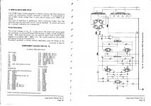
L1 is a choke having a dc resistance of less than 500 ohms, and about 20H center tapped; you can use a small output transformer, with the secondary left unused.
the 811a amp driven by 6BL7 cathode followers is the best amp and very easy to make, some people use mosfets but to me the 6BL7's are excellent and cheap. I made a amp using this circuit for a friend 17 years ago and the 811A's are still as when the went in, try that with 6550's.
600 volts is the max with 811A's, so you can bias them at 70 ma. 572b's could handle a lot more; but who needs more than 100 watts. chinese 811A's are cheap but you need to match them the RCA or Svetlana are mostly so close don't need to match.
Phil

811a amplifier
Multi
Referring to Multi's 811A amplifier, I seem to recall that you mentioned not using all the stages for your amp. Can you provide some detail of the amp's front end for us.
Multi
Referring to Multi's 811A amplifier, I seem to recall that you mentioned not using all the stages for your amp. Can you provide some detail of the amp's front end for us.
If I am going to continue my pursuit, it will be with the 6CB5. My transformers are already designed for 6-8 KT88s in UL. I just want to try different.
Regarding the center tapped choke, I can just use two 20H chokes side-by-side to get a center tapped effect.
Blair
Regarding the center tapped choke, I can just use two 20H chokes side-by-side to get a center tapped effect.
Blair
Regarding the center tapped choke, I can just use two 20H chokes side-by-side to get a center tapped effect.
The center tapped choke acts like a phase inverter. I know the design already has a PI, but two cascaded PI's just seems to work better. My driver of choice, and the one I will use here is two cascaded LTP's. Two seperate chokes will satisfy the Dc requirements, and the amp will work, but a single CT choke will work better. As stated, use a small P-P OPT. It may work fine with the secondary unconnected, or you may need a light load to keep it from ringing.
I found my second box of 6CB5's and I also have two of the rounded plate version. One is branded GE, the other RCA. They are RCA's.
Ejam
the Ef86 is just a pe-amp; I leave out all the resistors and caps only used for record cutting.
I will try to find a circuit i made with all the extra's left out.
I have used Sowter 2.2k A-A and also some c core transformers made by bob Sugden with cathode coupling 5k A-A 6db cathode coupling.
The original amp used a 10 kilo c core with 2.2k A-A
Mcintosh also made a similar amp 200 watts, but i think costs about $US7000 per monoblock to copy, the output transformers are made in the USA; I would have to look up the name of the firm, when i asked for a price think it was thousands, lots of winding's.
phil
The common cathode choke/transformer in the AppNo3 schematic would be acting as a transformer for augmented PI action I guess. Multi - what was the reference for that page?
There was a self-split PI technique using a cathode transformer that had a brief spot-light moment in the early 1950's - known as the cathamplifier.
Dalmura Pty Ltd
There was a self-split PI technique using a cathode transformer that had a brief spot-light moment in the early 1950's - known as the cathamplifier.
Dalmura Pty Ltd
trobbins
I got the circuit from the GEC Circuits for KT88.{ Application report No 3} The DA 41 circuit comes from the GEC Audio Frequency Amplifier design. {Audio Amateur Press}
I can scan the whole artical if you want.?
Phil
I got the circuit from the GEC Circuits for KT88.{ Application report No 3} The DA 41 circuit comes from the GEC Audio Frequency Amplifier design. {Audio Amateur Press}
I can scan the whole artical if you want.?
Phil
I'm fine with using a small OPT primary, but isn't there a grid drive circuit with no CT choke? Like some of the circuits referenced earlier?
Is there any criteria to a set of output transformers I need to look for to use as the CT choke? Example, I have access to a set of Fisher KX-100 outputs for $40.
Will they work?
Is there any criteria to a set of output transformers I need to look for to use as the CT choke? Example, I have access to a set of Fisher KX-100 outputs for $40.
Will they work?
811A circuit
I could not find my circuit so I was given this one.
The Stabilization net works need to be worked out depending on the Quality of the out put transformer. With the Sowter I used 4700Ohms and 470Pf across the plate resistor on the Voltage amp, most likely the cap value could have been smaller, you also need the resistor and cap net work on the primary of the out put transformer. i have used 6GU7's instead of 12BH7's or 12Au7's.
I find the value of the cathode resister on the voltage amp needs to be about 500ohms with the 6GU7 to get the correct biasing for the phase splitter or use a pot.
Phil
Attachments
Thanks Phil. I have the GEC 1957 document "An approach to audio frequency amp design". If you could scan the App report No.3 then I would certainly appreciate viewing it.
Ciao, Tim
Ciao, Tim
The attached "811A PP Amplifier MIKE" drawing has some serious mistakes or errors.
One is with 6BL7 cathode followers. There is +18,5 V at the cathode but 39k cathode resitor is connected directly to gnd.
The low end of cathode resistors should be connected to negative voltage instead of gnd.
Given cathode current 28 mA (14 mA/ tube) is impossible with 39k cathode resistor.
Second error is in GNFB-loop. There is no series resistor at all.
Guys
If you are looking for best 811 PP zero bias circuit I have ever heard,look no further than what Tom Tutay has done with the Altec 1570 amps.I have built two pair of these amps and they are phenomenal.
http://www.jumpjet.info/Pioneering-Wireless/eMagazines/VTV/VTV07.pdf
It should bring you right to the schematic but if it doesn't,scroll to page 17
Artosala;
my friend prepared this circuit for making an amp that is why there is no feedback resistor he still has to work out the value, as any one building the amp would have to, unless using the original output transformer.
The 811A is a zero bias triode using positive bias when run at low voltages; if using 812's negative bias, you connect the 39k? Resistors to the negative supply. The 811a 39 k goes to ground.
The advantage of this Grampian 811A amp over the Altec 1570 amps is the use of low voltage 600 volts and high current draw. The Japanese Nobu K Shishido used this same method using zero bias triodes in his single ended amps. Nobu used the 805 with 800 volts and 140ma for 50 watts single ended.
Phil
Another 1570B Modification
Multi
I came across this modified version of the 1570B by Greg Lunde which further simplifies the front end by reducing 3 stages (gain, splitter and driver) to a single differential stage. The differential stage is not the usual cascode with the grounding of the upper grids and the SRPP like bias arrangement. I would not use the 6SL7 in the cascode but a high transconductance tube such as the 6DJ8 or 6N6P. Anyway, for your interest and any comments welcome.
Attachments
Ejam
Thanks; hard to imagine that 6SL7's would have sufficient drive. Certainly best to use the 6N6 or 6DJ8.
Thanks; hard to imagine that 6SL7's would have sufficient drive. Certainly best to use the 6N6 or 6DJ8.
Cascode
Figured out that the cascode used grid-leak biasing of the upper triode to create self-bias as opposed to the usual fixed bias divider network usual employed. At quiescence, the upper triode is zero-biased, but when we input a signal, a charging current flows into the capacitor via the grid-leak, which lowers the voltage on the screen grid. The larger the signal, the greater the bias developed, which creates a compression effect on sustained passages. Great for guitars but not hi-end audio. Allen Wright's cascode differential would be the front end I'd think of using.
Figured out that the cascode used grid-leak biasing of the upper triode to create self-bias as opposed to the usual fixed bias divider network usual employed. At quiescence, the upper triode is zero-biased, but when we input a signal, a charging current flows into the capacitor via the grid-leak, which lowers the voltage on the screen grid. The larger the signal, the greater the bias developed, which creates a compression effect on sustained passages. Great for guitars but not hi-end audio. Allen Wright's cascode differential would be the front end I'd think of using.
...The 811A is a zero bias triode using positive bias when run at low voltages; if using 812's negative bias, you connect the 39k? Resistors to the negative supply. The 811a 39 k goes to ground....
Phil
It is clear that 811A requires positive grid voltage and current drive,
but with the circuit you posted it is not possible, or at least the distortion is very high. There is obviously a mistake in the drawing.
With the component values shown, the 6BL7 driver tubes are biased to some 0,24 mA / half. (18,5 V / 39 k).
I would bias them to some tens of mA's and allow the driver tube to swing to negative voltages as well.
- Status
- Not open for further replies.
- Home
- Amplifiers
- Tubes / Valves
- 30W sweep tube amp