I will meet Pete this coming weekend. We live about three miles from each other. He will have a room at LSAF, so I can bug him🙂
This is something that I do not think has been covered on this thread. How does power output differ from screen drive vs. straight pentode?
Here is where I'm going with this. Granted, I will seriously have to take up weight lifting when this is all said and done to move them.
I have a pair of power transformers that are going to deliver ~490-525VDC depending on the load and another pair that I can use in choke input for ~225V. I can use dropping CRC filters after the choke to get ~175V. That would be about perfect for the 6CB5 in pentode.
Into my 1.5K output iron, that should be a good combo with a standard Williamson front end.
I would think, and others have pointed out, that the usual 43% number is too much for a sweep tube. I believe that 43% was taken as the "magic point" for an EL34, and other tubes may work better with a different ratio. A sweep tube has a more sensitive screen grid than the typical audio tube.
43% seems to be the "magic number" of convenience of tapping off with sectioned primaries. Google for: "Radiotron Ultralinear Amps (1955)". This article states that tap-offs of around 20 -- 25% are best, and that there is a definite case of diminishing returns.
That's another reason why I don't favor this particular topology: there's no adjusting it once the OPT is wound. Better to use parallel lNFB as you can tweak it. I still doubt that these HD types even require it in the first place.
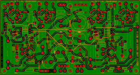
I modified a PCB design for 6JT6 and 6BG5 output tubes. Being 17watt tubes and similar in pin out, just a couple jumper options between the two. I had an idea but do not know how practical it is. With the odd voltage tubes, 16v, 18v, 21v heaters has any one tried a multi taped transformer?
310-70-0-310 at say 250mA for 400V B+ and 10.5-8.5-0-8.5-10.5 at 3Amp and 3.15-0-3.15 at 7.5Amp.....
That would cover most of the sweep tubes except for the 13BG5 flavor.
That would cover the *LU8, *JN6, *JM6, *JT6 tubes in the ~17Watt range.....
310-70-0-310 at say 250mA for 400V B+ and 10.5-8.5-0-8.5-10.5 at 3Amp and 3.15-0-3.15 at 7.5Amp.....
That would cover most of the sweep tubes except for the 13BG5 flavor.
That would cover the *LU8, *JN6, *JM6, *JT6 tubes in the ~17Watt range.....
Attachments
Running 13GB5's in UL Today with off-shelf Edcor Transformer
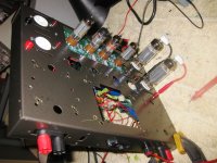
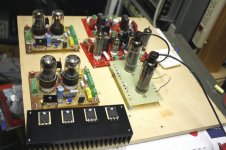
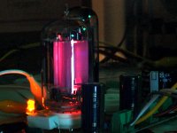
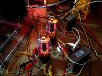
I am successfully today (so far) running 13GB5 pair push pull ultralinear into 2100 ohms p-p at 321 VDC plate, 324 VDC screen at 80mA quiescent current and -65 VDC bias.
B+ is from a 1:1 isolation transformer via voltage doubler. Driver tubes are $2 8GU7's, pre tubes are 50 cent 4EJ7's triode strapped.
I took an Edcor CXPP60-MS-4.2K and connected 8 ohms to the 16 ohm tap for the 2100 ohm load. I intially set the bias for 60ma/tube and it was stable. Bumped it up to 80ma/tube and still stable. That's 25 watts quiescent dissipation per tube. Bias still stable after playing at high volumes for awhile. No global feedback.
I have not run power tests as I get a huge hum when I connect the oscilloscope ground (probably a ground loop due to the mess on my bench). Amp is virtually hum free and plays music fine thru the one channel.
I need to measure screen current (tubes are NOT red plating or screening) and do some power checks in a day or so. I'll also turn up the bias and let you know when I see red on these 50 cent tubes.
Attachments
Last edited:
Tom,
How could you ever get a loop in that masterpiece🙂
I have a pair of power transformers that may be of interest for these sweeps if anyone is interested. They have dual 6.3v windings rated for over 6A each and a 250V winding good for well over an amp or two. They drove 8 X 8417s each.
How could you ever get a loop in that masterpiece🙂
I have a pair of power transformers that may be of interest for these sweeps if anyone is interested. They have dual 6.3v windings rated for over 6A each and a 250V winding good for well over an amp or two. They drove 8 X 8417s each.
Tom, that's great! Can't wait to hear more on actual measured performance. What is the UL tap ratio you are using?
Rene
Rene
I don't suppose they're lay-downs that'll fit in a dynaco chassis hole, i.e. 3.75 x 3" mounting holes??
Tom, that's great! Can't wait to hear more on actual measured performance. What is the UL tap ratio you are using?
Rene
Edcor states 40%. EDCOR - CXPP60-MS-4.2K
Of course, thanks, I'm not really all that good about doing more than 1 thing at a time, trying to do some work and this at the same time...🙂
I'll check on the Edcor line to learn what they have.
Rene
I'll check on the Edcor line to learn what they have.
Rene
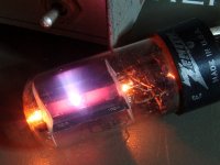
Is that an old Eico chassis?
Dynaco 70 chassis with paint on it. Driver board is a modified Dynamull board from Geek.
Hi Tom,
I sent you a PM. Yes, they are the right laminate size, but the bolt pattern is slightly bigger.
Blair
I sent you a PM. Yes, they are the right laminate size, but the bolt pattern is slightly bigger.
Blair
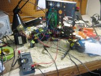
I thought I would post a quick update. I will be leaving on my yearly 2500 mile road trip next week and I won't be back until Memorial day, so there won't be any more progress until then.
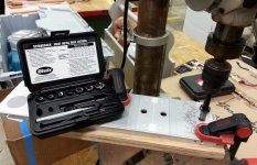
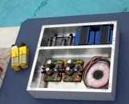
I will be building a two channel power amp for HiFi and guitar amp use, likely both at the same time (jamming to a computer generated backing track while computer recording). Expected power output will be in the 100 WPC range. The chassis is already designed, built by Landfall Systems, and in my possesion. A mock up was done to verify fitment before drilling any holes. The chassis divider was drilled last week in woodshop class.
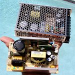
I rebuilt my old breadboard for testing. I have two of Petes driver boards and two of my own. I will make new ones if needed. I have output stage turret boards for 9 pin, octal, and 12 pin output tubes, a pair of big Edcor OPT's and plenty of smaller OPT's that I can experiment on. I found and mounted four BIG low capacitance mosfets that can blow screen grids in half without blinking. I will perfect this amp on the breadboard before building. The two main criteria are space (it has to fit the chassis) and efficiency (heat will be the limiting factor on power output). I have an SMPS for heater power (the small one in the picture).
The breadboard testing will determine which driver boards to use. Petes barely fit the chassis, mine are a bit smaller, and I can roll something new using smaller tubes. The choice of output tube must be made too. Some are already off the list due to diameter, height, or heater power. I will test screen drive, G1 drive, and both at the same time (hence 4 mosfets). The tube, driver, and type of drive choice is all about efficiency. I have seen screen drive work at very low idle currents. Idle current is important when you have 600 volts on the plates!
The fun will start next month, and I will start a new thread for it all. There will be some tubes that get tested just for fun too. Why, because there is a bigger amp to be built after this one.
I will be building a two channel power amp for HiFi and guitar amp use, likely both at the same time (jamming to a computer generated backing track while computer recording). Expected power output will be in the 100 WPC range. The chassis is already designed, built by Landfall Systems, and in my possesion. A mock up was done to verify fitment before drilling any holes. The chassis divider was drilled last week in woodshop class.
I rebuilt my old breadboard for testing. I have two of Petes driver boards and two of my own. I will make new ones if needed. I have output stage turret boards for 9 pin, octal, and 12 pin output tubes, a pair of big Edcor OPT's and plenty of smaller OPT's that I can experiment on. I found and mounted four BIG low capacitance mosfets that can blow screen grids in half without blinking. I will perfect this amp on the breadboard before building. The two main criteria are space (it has to fit the chassis) and efficiency (heat will be the limiting factor on power output). I have an SMPS for heater power (the small one in the picture).
The breadboard testing will determine which driver boards to use. Petes barely fit the chassis, mine are a bit smaller, and I can roll something new using smaller tubes. The choice of output tube must be made too. Some are already off the list due to diameter, height, or heater power. I will test screen drive, G1 drive, and both at the same time (hence 4 mosfets). The tube, driver, and type of drive choice is all about efficiency. I have seen screen drive work at very low idle currents. Idle current is important when you have 600 volts on the plates!
The fun will start next month, and I will start a new thread for it all. There will be some tubes that get tested just for fun too. Why, because there is a bigger amp to be built after this one.
Attachments

Have a great trip George. Looking forward to your Build when you get back. From the looks of it, it has that "MIG fighter electronics look" to it. Nice.
Without you and your STM (Sweep Tube Madness), I know I wouldn't be having nearly as much fun these days! The tests you did with the 13GB5 trioded went so well I had to connect it UL. Time will tell.
Without you and your STM (Sweep Tube Madness), I know I wouldn't be having nearly as much fun these days! The tests you did with the 13GB5 trioded went so well I had to connect it UL. Time will tell.
Ditto, have a great trip!
Can't wait to see the results of the superbreadboard and then the packaged final result. I'm still mulling over the near Class B operation and why it works with G2 drive but not with G1 drive, meaning the notch distortion. Notch distortion is an artifact of the leakage inductance in the transformer and exacerbated by Class B and its abrupt transition from conduction to non conduction without the other tube to "bridge" the current.
Hmm, unless, with G2 drive, you can have low idle current but somehow enough slop in the crossover region to have significant enough current flowing in both primary halves. That would be a really great dual gift since it's quite clear from published tube data that the G2 gm, especially for sweep tubes, remains quite constant over the range of voltages, certainly more so than G1 gm over the range of negative voltages. It might be very revealing to plot plate currents with G1=0 as now done but focusing on G2 voltages from +50 to perhaps -100. Might reveal the answer of the reported good behavior of this type of drive and low idle current.
Got a name picked out for the new thread when it comes?
Happy roading!
Rene
The tests you did with the 13GB5 trioded went so well I had to connect it UL. Time will tell.
I tested the 13GB5 pretty thoroughly in G1 drive mode. I will repeat the tests with the same one of Petes driver boards when the mosfet buffer is built. Since a sweep tube can be saturated to a low plate voltage in G1 drive mode without going into positive grid territory, adding the mosfet buffer shouldn't make much difference with static sine wave testing. It will however provide a baseline for when I use the same driver/mosfet buffer to drive the screen grid. I have lots of 13GB5's so they are a good candidate for testing, and might be used in the finished amp if they prove durable enough at 100 WPC. I have several other possible candidates too.
I'm still mulling over the near Class B operation and why it works with G2 drive but not with G1 drive
I can't say just how this stuff works, but I have seen it work, and played around quite extensively with screen driven sweep tubes several years ago. Most of my experiments were from a loud guitar amp perspective and used purpose built guitar amp OPT's. I dissected one of the OPT's and they have zero interleaving. They have one half-primary, then the entire 0-4-8-16 secondary, then the other half-primary.
I have since noticed that these OPT's respond differently to different tubes, and low plate resistance seems to be the key to good results. I used these OPT's in a push pull 300B amp and nobody believes that I got the OPT's for $16 each (I bought 200 and it was 15 years ago). I now have a pair of Edcors and a pair of Plitrons to test with. I have been listening to a G1 driven sweep tube amp (Pete's big red board with the cheap OPT's at 125 WPC) for about 2 years in a HiFi application, so I have a reference point sound wize.
Got a name picked out for the new thread when it comes?
No, I don't usually think that far ahead. I'll think of something.
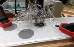
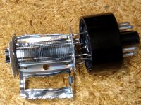
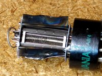
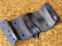
On a different note, last weekend I spent several hours outside sorting through my tube collection. I still have to thin the herd some more. In the process, I managed to drop a 6LX6 on the pool deck, and then step on the broken glass. After the temporary loss of vocabulary control, I got to pick the glass shards out of my foot with tweezers and wire cutters. It had to be a nice $30 sweep tube, not a half melted 6AS7. I saved the guts and have already removed the plate. I will post internal pictures when I get a chance. It has some unique internal fins on the plate to reduce secondary emission.
I have several hundred used 6AS7's. Some are pretty crusty looking. Once I get time to rig up an accurate way to test and match them, some of the bad ones will get "tested." I have been known to test some tubes a wee bit beyond their rated limits.
Note: The Chinese 6L6GC's and the Sylvania 21LR8 both still work good, the 6AX4 does not. It had a hole in the plate before I tested it, yet still tested good on two tube testers. The tube drop at reasonable currents, was in spec too, not any more. 6AX4 autopsy photo included.
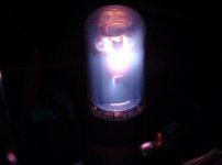
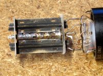
I had a bunch of gassy 6V6GT's. I stuck one in a SSE board and set the power supply on KILL. After about an hour of cranking out about 20 very distorted watts the cathode resistor blew, followed by the cathode bypass cap exploding. Tube autopsy was performed.
I have explained how you can overheat the screen grid in extreme screen drive applications leading to all sorts of blown parts. I was extracting about 125 watts from a pair of 6BQ6GT's when a tube arc blew up the tube, the mosfet, a bypass cap and a few resistors. Autopsy photos. Yes a wicked arc obviously ate the grid rod and a chunk of the plate!
And you think you are having fun!
Attachments
I can't say just how this stuff works, but I have seen it work, and played around quite extensively with screen driven sweep tubes several years ago. Most of my experiments were from a loud guitar amp perspective and used purpose built guitar amp OPT's. I dissected one of the OPT's and they have zero interleaving. They have one half-primary, then the entire 0-4-8-16 secondary, then the other half-primary.
I have since noticed that these OPT's respond differently to different tubes, and low plate resistance seems to be the key to good results. I used these OPT's in a push pull 300B amp and nobody believes that I got the OPT's for $16 each (I bought 200 and it was 15 years ago). I now have a pair of Edcors and a pair of Plitrons to test with. I have been listening to a G1 driven sweep tube amp (Pete's big red board with the cheap OPT's at 125 WPC) for about 2 years in a HiFi application, so I have a reference point sound wize.
Interesting! As a well experienced magnetics engineer (does anyone remember what a ferroresonant transformer is?}, I think the key to the beneficial but strange behavior may well lie in the low plate resistance. The time constant of an RL varies with the inverse of the resistance, exactly the opposite of an RC. If the flow of current is maintained more easily by the lower plate resistances involved then current flow is maintained and the nasty "notch" or discontinuous current is prevented.
Right now this sounds as good as anything! Some good testing with current probes, etc, should reveal the picture.
I love to see how we seem to be chipping away at this!
I'm still finding myself going back and forth between G1 and G2 drive. For about 35W using a 275V plate supply, the G2 voltage would need to be 300V P-P, a whole lot! That's what holds me back from G2 drive, otherwise all else points to G2 drive as a very good choice for Hi Fi with sweep tubes.
On the other hand, your experience plus that of others strongly suggests that transformer construction may be greatly relaxed.
All a trade off, huh! The story of engineering!
Rene
does anyone remember what a ferroresonant transformer is?
The brand name Sola comes to mind......
How about a saturable core reactor??? That's how you made a big (25KV 1/2 amp) regulated power supply before triacs were common.
I think the key to the beneficial but strange behavior may well lie in the low plate resistance.
I need to make some more recent measurements, but I believe that a screen driven amp will have a higher plate resistance than a similar G1 driven amp. I don't have real measurements to verify this, only the behavior of a zero feedback screen drive guitar amp cranked to 11.
I find that the G1 driven amp that I use now has good enough damping with just some local feedback around the output tubes (no GNFB). I have not made any output impedance measurements though.
I have to rip out the PC in my lab and take it with me. It won't be coming back, so I need to make a new one when I return. I plan to get my FFT analyzer working again even if I am limited to 96KHz before getting too involved with amp testing. I never made it work on the current computer due to issues with my high end sound module. Creative sells a very expensive box, then drops support for it.....
Don't you just hate that!Creative sells a very expensive box, then drops support for it.....
The brand name Sola comes to mind......
How about a saturable core reactor??? That's how you made a big (25KV 1/2 amp) regulated power supply before triacs were common.
I'll see that and raise you magnetic amplifiers! I used high frequency units to make SMPS (before they were know as SMPS) when it was hard to get BJTs to survive extreme DF swings (before the days of the modern MOSFET). What I did was to implement a square wave inverter, constant duty cycle, and perform the PWM with the mag amp.
Glad we don't need to that anymore!
So, back to why G2 seems to allow near or actual class B without notch distortion or expensive transformers, maybe there is some sort of different and strange behavior around G2=0 that permits this.
Who will be the first to find this Bigfoot!
Rene
Who will be the first to find this Bigfoot!
I don't know, but I can assure you who will be the first to melt a few sweep tubes in the quest.....the 6BQ6GT shown a few posts back counts as #1.
- Status
- Not open for further replies.
- Home
- Amplifiers
- Tubes / Valves
- 30W sweep tube amp