Most of the complexity was power supplies (he was doing switchers in 1977!) and control circuitry- the signal circuits are pretty simple. For example, the EA-230 uses an input/driver stage based on the classic Williamson, but with a cathode follower to drive the screens. He also uses feedback from the output tube plates to the driver stage which reduces distortion in two ways- the source impedance from the output tube plates to the output transformer is lowered (reducing transformer distortion), and the overall output stage/driver is linearized through the feedback.
A lot of clever stuff in his circuits, pretty simple, but clever and effective.
A lot of clever stuff in his circuits, pretty simple, but clever and effective.
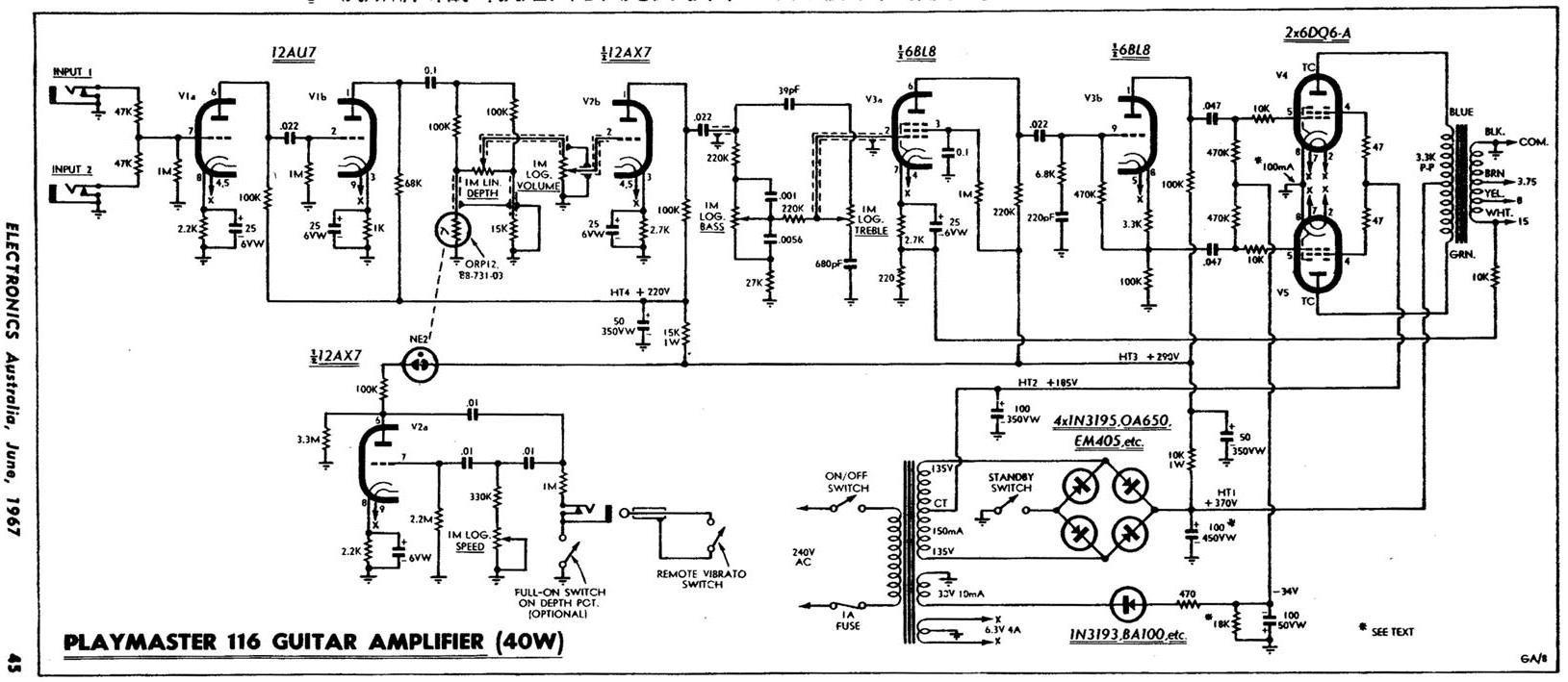
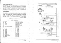
FWIW here there are 2 examples of 1966 vintage commercial 6DQ6 powered Guitar amplifiers.
With all the proper voltages, designed to last.
190V screens, 380V plates, fixed bias, conventional drive.
Were built by the 100's and many still survive to this day.
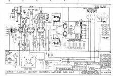
Straight from "Australia/NZ classic valve amps" Classic ANZ Valve Guitar Amplifiers (thanks Roly 😉 )
A stereo/active reverb 30+30W amp:
With all the proper voltages, designed to last.
190V screens, 380V plates, fixed bias, conventional drive.
Were built by the 100's and many still survive to this day.
Straight from "Australia/NZ classic valve amps" Classic ANZ Valve Guitar Amplifiers (thanks Roly 😉 )
A stereo/active reverb 30+30W amp:

Howdy, Michael. That's funny! I looked up the Collins, cool rig. though not now on the air, we do have a Tempo tube HF rig using, you guessed it, sweep tubes for the final PA. Rugged as all getout.
Have to get an antenna up (I have the space, thinking Windham multiband)
Now, if we could only convert the Collins to audio!!... 🙂
Do you still have your license? I am very active on 3.880 75m AM phone..I run a Johnson Valiant 250w thru a 80m dipole up about 75 feet in a V fashion..I receive with a Collins R390a or a Hammarlund SP-600, or an HQ180a, at any given time. The 390a I did the product detector upgrade where I can get good sound slop bucket which is,side band ..LOL
73
N8TPI Mike
So, folks, back to the "specs" for my project to be. I'm sure that I want to stay in the 30-50W per channel range because I simply don't need more, which will be reflected in lower iron costs, lower PS costs (however those are implemented, straight linears or SMPS, still there is a cost per watt involved) and size (this will be in our living room). G2 drive is technically attractive because I've never done that, not even with RF stuff, past very low level AM modulation. But it seems that its advantages are mostly for the monster amps. Does not mean that I won't do that, just that it does not appear to be the "default" technique given my relatively low power needs. Still, it's appealing and if its benefits extend beyond merely being able to wring out huge power, where it yields net hi-fi benefits, I'm in.
Barring that, it seems that G1 drive with some suitable linearization (UL, lots of local loops, all of them, whatever else is available) may be the more appropriate for me.
I am obviously still thinking out loud here, my mind is by no means made up.
What I have enjoyed, and will continue to enjoy, is the tremendous discussion, ideas, willingness to contribute, hands on activities that this and other threads engender. This is truly a place for people who are passionate about our hobby.
I hope the posts continue and I will continue to think and ponder and post. I promise when the project actually starts that y'all will be kept updated.
Advice, please: will it be best to then start a new thread?
Thanks to all, keep it up!
Rene
I've been exploring the same thing. Got all the parts, but all the metal work has me stalled. I'm feeling 6AV5, 6GV5, or 22JF6 although the *JF6 is a bit mysterious to me, but I suspect they may work. I've got a mono 15w amp that I hope to experiment with first before I proceed.
Keep posting here on your progress!
Keep posting here on your progress!
A little note on construction of the 6CB5. I ordered 8 from AES and got three variations. No big deal for initial fire up and tests, but there are more than two manufacturers.
There is a quad of the grey plates with squares but out of them, a single with a rounded bend on the plate with no vent holes, and three black plates with no holes.


There is a quad of the grey plates with squares but out of them, a single with a rounded bend on the plate with no vent holes, and three black plates with no holes.
Cool, great to know! I wonder if the two gray ones are of the same manufacturer but different revisions. I don't suppose we can be so lucky as to score date codes and possibly manufacturer's (as opposed to branding) identification?
George had indicated that the Sylvania units had the apparently more massive plates compared to the RCA, though not necessarily by a lot.
Thanks again!
George had indicated that the Sylvania units had the apparently more massive plates compared to the RCA, though not necessarily by a lot.
Thanks again!
The black plate tubes at the top of the picture are Sylvania, The grey plate tubes at the bottom are RCA. I think your rounded plate version is also an RCA. Look at the pictures in post # 168 and 171 in the AES thread.
http://www.diyaudio.com/forums/tubes-valves/128533-tube-sale-aes.html?highlight=tube+sale+AES
I just went through my posts in the AES thread, and all my 6CB5 testing was done with RCA's
I have used screen drive for big stuff since it is easy to get at least 50 watts from a pair of even the smallest sweep tubes. Also most "regular" type tubes don't seem to work well with screen drive. I did find a small tube that works with screen drive, the 6JQ6. It is a 9 pin miniature vertical sweep tube that was on the dollar list, so I lit up a set. 30 watts from a pair of small tubes is not too bad.
http://www.diyaudio.com/forums/tubes-valves/128533-tube-sale-aes.html?highlight=tube+sale+AES
I just went through my posts in the AES thread, and all my 6CB5 testing was done with RCA's
G2 drive is technically attractive because I've never done that, not even with RF stuff, past very low level AM modulation. But it seems that its advantages are mostly for the monster amps.
I have used screen drive for big stuff since it is easy to get at least 50 watts from a pair of even the smallest sweep tubes. Also most "regular" type tubes don't seem to work well with screen drive. I did find a small tube that works with screen drive, the 6JQ6. It is a 9 pin miniature vertical sweep tube that was on the dollar list, so I lit up a set. 30 watts from a pair of small tubes is not too bad.
I want to stay in the 30-50W per channel range........I'm feeling 6AV5
I had no problem squeezing 80 watts from a pair of 6AV5GA's. 30 to 50 would be easy. There is also a 6V6 sized 6AV5, the 6AV5GT. It should do 30 or 40 watts easy, and nobody wants them so they should be cheap.
still there is a cost per watt involved
If you look at "by the book" tube audio design there seems to be a log relationship between dollars and watts. My mission has been to find the outliers. Just considering tubes, the 13GB5 is hard to beat 75 cents per tube and I have seen 150 watts flow from 2 of them without melting. They will light up just fine from the two 6.3 volt windings on an Antek toroid in series.
Screen driven pentodes; zero bias triodes
Zero Bias triodes; when a pentode is driven on the screen it becomes similar to an 811A Zero bias triode. KT88’s and 807’s screen driven were used by radio amateurs as modulators for transmitters
You can get up to 120 watts from 807’s, 150 using KT88’s or up to 200 watts using a DA 41-42 or 811A. The 811A can give very good audio quality running at 100 watts, with 600 volts and 70 ma current draw, you could also use 805’s
The 811A and Da41-42, 805’s where used in record cutters.
Svetlana and RCA 811a's last for many years at 600 volts.
Phil
Attachments
What kind of choke is that in L1 on the KT88 schematic? It looks a lot like the MC-240 schematic without the "Williamson" type front end.
The more I see these screen drive topologies, the more hesitant I am to proceed. They look a bit tricky.
The more I see these screen drive topologies, the more hesitant I am to proceed. They look a bit tricky.
Here is what I'm beginning to see as I continue to think whether G1 or G2 drive for my sweep tube amp.
As already discussed, sweep tubes generally have higher G2 gm than "ordinary" tubes. They are also inherently rugged, nothing wimpy about them.
Speaking specifically of the 6CB5, its G1 gm at, say, 200V plate in the subscript 1 region is less constant than its G2 gm. To be sure, the G1 gm is very, very high but a gm of 4ma/volt for G2 ain't bad. Just from the data, this G2 gm slowly decreases to 3ma/v at the lower G2 voltages, while the G1 gm starts at about 20ma/v but is down to less than 1/2 that at the more negative G1 voltages. Just from that alone, one might conclude that, indeed, G2 drive is more linear than G1 drive.
These comments do not appear to be applicable to the 6DG6 where G2 gain is not nearly as constant as for the 6CB5, tellling me that not all sweep tubes are created equal.
Just another little nugget to add to the thinking process here.
OK, time to go to church, I'm thinking of starting a new thread devoted exclusively to G1 vs G2 drive for the 6CB5s of this world.
Rene
You'll find a correlation to perveance. High perveance (and low G2 max voltage) almost always means better performance in screen drive, assuming a good, solid drive like a source follower.
Is the 6DG6 ever used as a sweep tube? I've never seen that before.
Is the 6DG6 ever used as a sweep tube? I've never seen that before.
Boy, what a typo! Try 6BQ6, the 6DG6 is basically a 6V heater version of the 50L6 of AA5 fame. Sorry about that. Someone else on this same thread pointed out that the 'BQ6 is really a 6L6 redone for sweep service, which would explain both its high G2 voltage rating and the marked difference in G2 gm behavior (the shape, not necessarily the values) to the 'CB5.
I will continue to look thru reasonable (meaning price and plate PD) sweep tubes. I kind of like the octal T12 types and I think plate caps are cool so I'll stick to those types for my amp.
I will continue to look thru reasonable (meaning price and plate PD) sweep tubes. I kind of like the octal T12 types and I think plate caps are cool so I'll stick to those types for my amp.
Is the 6DG6 ever used as a sweep tube? I've never seen that before.
The 6DG6 is the same as the 6W6 and in fact some tubes are dual marked. The 6W6 is intended for audio amp and VERTICAL deflection service, so the 6DG6 can be called a sweep tube, but it is not a HORIZONTAL sweep tube.
Vertical sweep tubes (sweep the beam up and down across the TV screen) are operated as linear amps. They can be thought of as an audio amp operating at a single frequency (50 or 60 Hz) but they are fed a sawtooth waveform which is harmonically rich, and must reproduce it faithfully to get round circles on the TV screen. I learned at an early age that the entire vertical sweep circuit can be lifted from a TV set, and by disabling the oscillator feedback and connecting a speaker where the deflection yoke goes, be used as a guitar amp. Some work good enough to be HiFi amps.
Thr horizontal sweep circuit is operated as a grid controlled switch. A square wave is applied to the grid, and current is limited by the screen voltage. This current is applied to the flyback transformer, which feeds the horizontal sweep coils in the deflection yoke, moving the beam from left to right across the TV screen. The current is switched off, returning the beam to the left edge of the screen, and creating a huge high voltage pulse that is stepped up to as much as 30KV, rectified, and fed to the CRT. This works like the ignition coil in your car. None of these parts except the tubes are useful in audio.
This thread is about horizontal sweep tubes. Vertical sweep tubes do make good audio amps (since they ARE audio amps) but with very few exceptions, don't like screen drive. The biggest vertical sweep tubes are good for maybe 30 watts in push pull. The smallest horizontal sweep tubes start at 50+ watts in push pull.
Note: some of the very early horizontal sweep tubes in tiny black and white TV sets aren't really sweep tubes at all. Before the sweep tube was developed, other tubes were repackaged as "sweep" tubes. The 6BG6 is one of these. It contains 6L6GB guts and thus doesn't like screen drive.
Octal will definitely limit you for high perveance sweep tubes!
UH, the MACK DADDY of all sweep tubes, the 6LW6 is octal. It is a relative of your friend the 6LF6.
The little 6BQ6 comes in two flavors, small (6BQ6GA), and smaller (6BQ6GT). I have "tested" both flavors in screen drive, and they work. The tiny 6BQ6GT was where I learned the limitations of screen drive by setting the screen grid on fire. I was extracting 110 watts from a pair at the time, so it is to be expected.
Nonetheless, I think either of us could name 30 high perveance horizontal sweep tubes with novar/magnoval or compactron bases, but maybe 4 or 5 in octal.
Indeed! unfortunately, they've been "discovered" and are pricey. 🙁
I just did a very quick look-see at G2 drive using the 6CB5. With only a G2 swing in the order of 260P-P one can easily get well in excess of my goal of 30W, with only a plate supply of 300V. The G2 power does not look unreasonable, nothing that a good MOSFET source follower could not easily handle.
Even at that, the G1 bias certainly could be set at some value less than zero for tweaking purposes. Hmm! Looking good!
But I have a whole lot more homework to do on all this. Certainly would solve the proper G2 voltage issue while in UL mode, plus make the OPT (should, anyway) less costly and somewhat less critical of design. Maybe even the layer wound, not necessarily balanced Edcor or Hammond would be adequate... But I am a magnetics engineer and will tend to be more of a purist in that, those imbalances just grate on me and it's the reason why I'm thinking toroidal transformer.
Still trying to understand how some of you have gotten good sound results while operating in what seems to me very, very close to pure class B1 and yet seem to be avoiding cross over distortion (due to the leakage inductance of the transformer, unless very, very carefully designed). Perhaps it really is not classic Class B but something different happens close to the plate current cross over and there is some sort of sufficient overlap between the two tubes? Just speculating, not making any statements, not ready yet. 🙂
OK, family time, I'll be off this thing for a while.
Thanks!
- Status
- Not open for further replies.
- Home
- Amplifiers
- Tubes / Valves
- 30W sweep tube amp