I now have a pair of transformers that can be used with choke input for ~520-540VDC @ 500+mA along with a pair of 200W 1.5K output transformers. I'd like to try a quad of the 6CB5A tubes with all of this......How does the distortion compare to "audio" tubes?
I see no reason why this wouldn't work. 4 tubes per channel should be plenty for 200 watts or so. Your power supply can only generate 270 watts of continuous DC output (540 volts * 0.5 amp) which will only support about 200 watts of continuous full power output, assuming a 75% efficient output stage. If you use a good low ESR cap in the power supply, the amp should be more than capable of 400 watt peaks (200 WPC).
All the distortion numbers I have posted in my experiments have been with no feedback whatsoever unless I stated that I was using "Schade" type feedback (Petes red boards). Sweep tubes and KT88's seem to generate similar distortion numbers. My FFT analyzer hasn't worked in a coule of years, so I don't have individual harmonic plots. The bigger sweep tubes sound more dynamic. It has been stated earlier in this thread, that the poster preferred to use a bit of global feedback, and no local feedback. Petes boards can do either, or both. My tastes lean toward some local feedback, zero global feedback.
I built a breadboard amp using the driver boards I designed for the 6L6GC in AB2 thread. I ran that board with everything from DHP's (the 307A) to triode wired KT88's and 7403's, and sweep tubes in sizes from tiny, to the mighty 6LW6. I did not try the 6CB5. Of all the tubes, I liked the trioded 6LW6 the best, except they kept blowing up. I plan to start some new experiments in pentode mode to see what works the best for me in my new amp. I could stick some 6CB5's in and see what happens.
What voltage can the 6CB5A handle as a triode?
I have never tried the 6CB5 in triode, so I don't know how it works. there is a thread on here that talks about an SE amp using a 6CB5 that sounds better than a 300B.
Thanks George!
Sounds like a plan. At $30 a quad shipped, it is a nice option. Plus, I can just leave space for a few more tubes if I choose to go with KT88s in the end.
What kind of drive is needed to drive a quad of these tubes to full power? Someone recommended the 6GF7A to me as a driver.
Thanks!
Blair
Sounds like a plan. At $30 a quad shipped, it is a nice option. Plus, I can just leave space for a few more tubes if I choose to go with KT88s in the end.
What kind of drive is needed to drive a quad of these tubes to full power? Someone recommended the 6GF7A to me as a driver.
Thanks!
Blair
This might be a good use for the Circlotron idea, where circuit simplicity is traded for floating power supplies. Connecting G2's to signal ground gives complete freedom of G2 DC voltage and the equivalent of 50% screen tapping - close enough to "UltraLinear". You will need big drive voltages, but small currents. Even 6SN7 size drivers can provide plenty of slewing current to a Circlotron or McIntosh (same same).
Thanks,
Chris
Thanks,
Chris
I have never tried the 6CB5 in triode, so I don't know how it works. there is a thread on here that talks about an SE amp using a 6CB5 that sounds better than a 300B.
Sounds like this thread:
http://www.diyaudio.com/forums/tubes-valves/179701-se-6cb5a-amp-6n7-driver.html
jeff
I see no reason why this wouldn't work. 4 tubes per channel should be plenty for 200 watts or so. Your power supply can only generate 270 watts of continuous DC output (540 volts * 0.5 amp) which will only support about 200 watts of continuous full power output, assuming a 75% efficient output stage. If you use a good low ESR cap in the power supply, the amp should be more than capable of 400 watt peaks (200 WPC)
Thanks George! The big difference in the 6cb5 and 6lw6 is price! I'm going to get a few quads and start on this once my pieces start arriving. My supply should be good for more than 500mA with a choke input, and this is HiFi, so I bet I never get up over 50-100W unless I'm hosting a party and we need sound in the back yard🙂
I will spin off of this thread for the amp build.
Is there a preferred brand of 6CB5A tubes? RCA, GE?
Thanks!
Blair
Last edited:
At $30 a quad shipped, it is a nice option.
AES still lists them at $4.40, Vacuumtubes.net and ESRC both show $5 each.
What kind of drive is needed to drive a quad of these tubes to full power? Someone recommended the 6GF7A to me as a driver.
Most sweep tubes can do their thing without needing or wanting AB2. This means that the grid will not draw current, and if we consider only pentode, or possible UL mode, Miller capacitance shouldn't be an issue, so it comes down to whatever you want that can deliver a clean drive VOLTAGE. I have not needed to use mosfet buffers for conventional G1 drive even when driving 4 or 6 tubes. Mosfet or cathode followers are mandantory for screen drive. I prefer a mosfet, but the big half of a 6GF7 (a tiny vertical sweep tube) should work too.
My driver board uses a 6SN7's in LTP, feeding 6SN7's in LTP, feeding mosfet followers and it works just fine. It is overkill here. Pete made two driver boards using pentode LTP's. The "big red board" uses a 7 pin pentode like the 6CB6. I think I settled on the 6GU5 hexode for a bit more gain. The "little red board" uses 9 pin pentodes in LTP. I used 6HB6's because they are $1 and a pair will put out 15 watts. Yes, they are sweep tubes! I think Pete used 12BY7's or 12GN7's.
Any of these designs will do fine with 6CB5's or any other horizontal sweep tubes in G1 drive. Screen drive requires a lot more drive voltage which your driver tubes must supply cleanly, and some drive CURRENT, which the mosfet followers will supply.
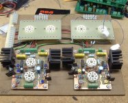
I am including some pictures that I happen to have on my work computer.
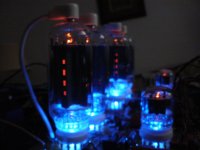
The breadboard is my 6SN7 LTP --> 6SN7 LTP --> mosfet follower board. It was designed to drive anything. I believe this is the 6LW6 triode incarnation. I think the picture was taken as I took it apart.
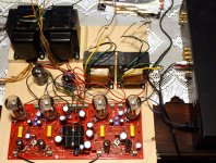
The Flamethrower 250 breadboard is a 125 WPC sweep tube amp built with Petes big red board. It still exists and I use it to rattle the neighborhood through my 15 inch OB coaxials. The output tubes are 6HJ5's which are still $4 each and don't need a plate cap.
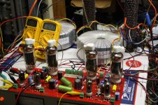
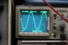
504 watts from Petes big red board with 35LR6's. This is the board under power.
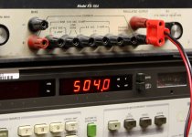
The watt meter reading.
The scope trace at 504 watts. Notice the slight onset of clipping. 5% distortion occurs at 525 watts.
The big difference in the 6cb5 and 6lw6 is price!
I got all of mine on Ebay back when they were $5 each. The price went up when someone published an article in Glass Audio for a 6LW6 180 watt amp.
and this is HiFi, so I bet I never get up over 50-100W
A point that is often forgotten, is that even if you turn the volume up until the amp starts clipping, the AVERAGE power will be 10 to 20 watts or less.
Is there a preferred brand of 6CB5A tubes? RCA, GE?
The important thing, is that all the tubes must be the same. It's been a while since I played with the 6CB5. I will look at my collection to see if anything stands out. I first met the 6CB5 back in 1969 when I restored an old color TV that was made in 1954. The 6CB5 was missing and I got the old TV running with a 6146A in the socket (pins rewired). After the second 6146 blew, I got a real 6CB5. I forgot all about this tube until the AES tube sale about 5 years ago.
Attachments
Howdy, Folks: well, back in town, been chasing after some business but now can spend time on this again and been catching up on the posts.
For what it's worth, my UL analysis is suggesting to me that the 6CB5 (and similar tubes) will be happier with around a 25% tap as opposed to the more classical 40%. Still, I did not see anything nasty happening with a 40% tap just that some power for a given plate supply voltage will be left on the table. Still, as has been repeatedly mentioned here, these sweep tubes are capable of a whole boat load of power. I'm still thinking in the 30-50W for my needs but am impressed with the actuals that can be obtained. Could mean many happy years of listening for me and never have to replace anything.
So I'm back to either going forward with the original concept of G1 drive UL, full differential all the way back to the line input (with CCS loaded LPT), lots of local feedback (including Schaede for the outputs) and mild global, or else further explore G2 drive but still remain in the 30-50W range.
A first look at the transfer curves shows G2 drive to be quite reasonable to obtain at my power levels, no funky looking kinks or nastiness. I would be concerned about sending the G2 too far below, or even at all below, the cathode, just because I see nothing in the data sheet which allows that. Should be fairly simple to prevent the drive from swinging that way by simply DC coupling and referencing things correctly, but that is an off the cuff statement, the engineer in me is going to demand rigorous analysis.
BTW, as far as I can tell, for those wanting to know about manufacturers of the 'cb5, it appears that only RCA and TungSol made these though others could have branded it. GE does not appear to ever have neither made it nor even marketed it. My vote is with the RCA version.
Rene
That's interesting regarding the UL tap percentage.
Is it possible to use the UL taps at 43% and then clamp your screen voltage down to 175V or so using a Zener string or HV regulator?
Is it possible to use the UL taps at 43% and then clamp your screen voltage down to 175V or so using a Zener string or HV regulator?
I would be concerned about sending the G2 too far below, or even at all below, the cathode, just because I see nothing in the data sheet which allows that.
I have seen the screen go to -160 volts on 6LW6 without issue. There is likely no mention of this in the data sheet because the old tube engineers of days gone by never dreamed that there would ever be guys wiring their beloved tubes up to silicon fuses and abusing them in new and twisted ways. Silicon..?????..Whazzat.
For what it's worth, my UL analysis is suggesting to me that the 6CB5 (and similar tubes) will be happier with around a 25% tap as opposed to the more classical 40%.
It makes sense to me. The screen grid sensitivity of the average sweep tube is much greater than say a 6L6GC, so less movement in screen voltage is needed for the same effect on plate current.
Is it possible to use the UL taps at 43% and then clamp your screen voltage down to 175V or so
I would think that any type of hard clamp would cause instant clipping like distortion at the instant it engaged. When I do these kinds of screen drive experiments, I typically have adjustable power supplies on everything. The voltage knob on the power supply that feeds the screen drive mosfet becomes the "max power" control. When the driver attempts to pull the screen up higher than you have the power supply set for, instant clipping occurs. This keeps the screen grid meltdown from occurring, but sounds worse than the plate supply clipping.
For those who really want to venture off the beaten path, check out these threads. Variable UL has been done before.....
http://www.diyaudio.com/forums/tube...cussion.html?highlight=adjustable+distributed
http://www.diyaudio.com/forums/tube...-design.html?highlight=adjustable+distributed
When i saw your post,I honestly thought you were talking about the Collins 30 series RF amplifier that we use in ham radio for low bands.Howdy, Folks:
While not new to tubes, I am relatively new to the DIY hobby of designing and building tube amplifiers.
I have been in the downhole oil/gas industry for several decades, designing high temperature analog and power electronics, with the added requirement of very high reliability (which flies in the face of the high temperature, fun, huh!!).
Wanted to do something challenging and a little different. After reading numerous vintage articles (Crowhurst and the likes), I have decided to go the UL route. After looking at many candidate tubes, the sweep and RF transmitter tubes started to make a lot of sense. Finally have settled on the 6CB5 (after seriously considering the 1625, 12V version of the 807). Had to design a simulation tool to investigate its transfer and plate curves for UL operation, that was fun in itself.
Anyway, nothing concrete yet except for the overall topology of full differential from the input to the output transformer, as much DC coupling as possible and lots of local feedback loops, with no loop covering more than one RC constant.
Solid state CCS don't bother me a bit, they will be used instead of pentodes (no concerns about heater/cathode potentials plus lower minimum voltage) and modern SMPS for heater and likely +B.
I'll be concerned more about proper circuit design, things like operating points, phase shifts, levels, in short, the basics all around.
While quite capable of designing and building my own output transformer, not really looking forward to that. I am attracted to a toroidal design (all things equal, best coupling, lowest core losses and magnetizing currents) and would welcome any comments on providers out there. I know of Plitron and the Dutch equivalent but not of any others.
Anyway, nothing concrete for now, no details but the floor is certainly open to any pertinent suggestions and thoughts and ideas and, most of all, encouragement I can get from the group.
Oh, yes, what are you kind folks' ideas on schematic capture/sketching programs? While I have PCAD, it has no tube libraries and am loath to create any, so if there is something already out there, I would much prefer not to have to invent anything.
Thanks!
Rene
Collins 30S-1 Linear RF Amplifier
Re the post about clamps for the screen, I wonder if that could be my fault for having mentioned zeners. If so, a little clarification: the use of the zener I have in mind is as a dropping mechanism, so the screens of the 6CB5 can be fed with their proper voltage while the plates are running at, say, 300 or so volts. With the UL tap, the G2 voltage will be the instantaneous plate voltage modified by the tap ratio, MINUS the zener drop. As George already pointed out, one must be careful when using this scheme not to allow the screen voltage to suddenly drop off the face of the earth as the plate voltage swings low during heavy tube conduction. A clamp would keep a tube from melting but will sound horrid!
Howdy, Michael. That's funny! I looked up the Collins, cool rig. though not now on the air, we do have a Tempo tube HF rig using, you guessed it, sweep tubes for the final PA. Rugged as all getout.
Have to get an antenna up (I have the space, thinking Windham multiband)
Now, if we could only convert the Collins to audio!!... 🙂
Have to get an antenna up (I have the space, thinking Windham multiband)
Now, if we could only convert the Collins to audio!!... 🙂
OK,
I'm invested to some degree in this now. I did elect for the 6CB5 tubes because they are octal and if this fails, I can just punch some extra holes for KT88 in UL.
I got an 8 pack of the power tubes, and a sleeve of 6GF7A tubes. I located and purchased another western electric power transformer, and my output iron is on the way. I have a pretty good assortment of choke options as well.
Is it best to use a separate power transformer for the screen supply? Would a choke input supply be best for regulation?
Now, I need to lay low and let the financial devastation settle befor I'm served papers....LOL!
Schematic for sweep tube amps. I tested this one and it is slated to go into a chassis this summer along with a phono-preamp. I found a nice slab of Brazilian cherry to try. I'm going to boost the B+ with an extra transformer and power supply PCB. I decided on 6.6KRaa 60 Watt iron, I had used the 6.6k 40 watt iron in other builds and prefer it over the 4.3KRaa iron. I prefer the larger class A operating area.
Attachments
BTW, as far as I can tell, for those wanting to know about manufacturers of the 'cb5, it appears that only RCA and TungSol made these though others could have branded it. GE does not appear to ever have neither made it nor even marketed it. My vote is with the RCA version.
I went through about 20 tubes. I do have several GE branded 6CB5A's in GE boxes. The tubes appear to all be of RCA or Sylvania manufacture. I have several others branded RCA, Zenith, or Sylvania. All seem to be RCA or Sylvania made. I have no TungSols.
Both look about the same construction wise. The Sylvanias have the typical black rectangular plates with no holes, and huge grid heat radiators. The RCA's have grey plates with square holes and small grid radiators.
It would be hard to guess which could take the most abuse without testing, but based on looks alone, I would give a slight edge to the Sylvanias. They look the same as some other Sylvaanias that took a lickin and kept on tickin.
Duh, I wrote Tung Sol meaning to say Sylvania! Thanks for the correction. That's something, that you found GEs, tried as I could, I cannot find a GE datasheet for the critter anywhere, and could not find any evidence of GE branded tubes either. But, you did so they exist, while your physical evidence seems to support that GE never made any.
So, at least one thing, with the apparent sources being limited to RCA or Sylvania, this might mean a smaller distribution of properties among the available population. Might being the operative word.
Onward thru the fog!
So, at least one thing, with the apparent sources being limited to RCA or Sylvania, this might mean a smaller distribution of properties among the available population. Might being the operative word.
Onward thru the fog!
I will try to hook some up before I leave for the 2500 mile road trip I take every year in the middle of May. There is a 3 day stop in Dayton for a little ham radio...and audio ....and TUBES...show. Wife will be in the car on the return trip, so I can't hide too much stuff.
I have a rather small samlpe size. There are more in this house somewhere. The TV set that had the 6CB5 was an Emerson branded RCA. I don't know if GE was making color TV's yet, so it's possible that they didn't make the tube. I worked in a TV repair shop from 1968 to 1971, then at an Olson store in 71 and 72 and I don't remember ever seeing another 6CB5. Most early color sets used a 6DQ5 or a 6CD6.
your physical evidence seems to support that GE never made any.
I have a rather small samlpe size. There are more in this house somewhere. The TV set that had the 6CB5 was an Emerson branded RCA. I don't know if GE was making color TV's yet, so it's possible that they didn't make the tube. I worked in a TV repair shop from 1968 to 1971, then at an Olson store in 71 and 72 and I don't remember ever seeing another 6CB5. Most early color sets used a 6DQ5 or a 6CD6.
The schematics to the old Berning amps are on his web site.
Tube amplifiers for high-end audio by The David Berning Company
Tube amplifiers for high-end audio by The David Berning Company
I looked his amps up based on an old post by SY I found. That looks pretty complex and far beyond my comprehension. I see posts that screen drive assists with linearity. Do these tubes not perform well in straight pentode mode?
Last question before I quit thinking about this today. Back to the original post, how would these 6CB5 tubes do at 350V B+ in UL? Would the screens survive? What kind of output power could be expected from that B+ in UL?
Thanks!
Last question before I quit thinking about this today. Back to the original post, how would these 6CB5 tubes do at 350V B+ in UL? Would the screens survive? What kind of output power could be expected from that B+ in UL?
Thanks!
Last edited:
- Status
- Not open for further replies.
- Home
- Amplifiers
- Tubes / Valves
- 30W sweep tube amp