
Indeed. I need to form a proper REW workflow.Great!
Adjust vertical scale to around 50 dB range for meaningful graphs. (you used 210 dB in your graph!)
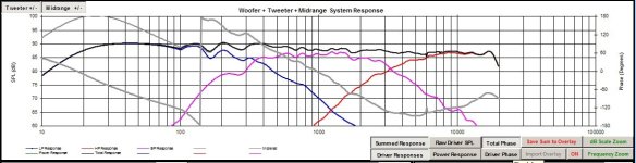
overall 1.5m and 2.5m
tweeter -12dB, mid -10dB, asymmetrical low shelf 60/30Hz (LT), no other DSP
Xovers LR4 at 250 and 3k


tweeter -12dB, mid -10dB, asymmetrical low shelf 60/30Hz (LT), no other DSP
Xovers LR4 at 250 and 3k
No values shown, just responses. Don't look too close below 100hz, That's just simmed from a straight line response below 100hz, and with some boost. I think with the boost, it would look like the flatter response.
Attachments
Last edited:
More details from 2nd attempt crossover, measured at 2,5m in-room. Are red and green L/R speakers?


Next time, please use just one speaker and take measurements with mic at midrange height, distance 60-80cm. This way you will reduce room effect. Measure each way only and as 3-way. Then invert the polarity of midrange and measure the system again. Use 6-9ms right window and 1/6 smoothing. My examples below (LR2, no invert test).To see distortion use 90dB mean spl at 1-2m.


- Room is playing too big role to see step response and crossover match clearly
- I would let tweeter play louder, or at least the bump between 800-1500Hz should be tamed. Yhis is on-axis long gating so it reflects listening window estimate in VCAD.
- I think low bass has too much lift, but room boost is high as well
- obviously eq for each driver and delays must be tuned
Next time, please use just one speaker and take measurements with mic at midrange height, distance 60-80cm. This way you will reduce room effect. Measure each way only and as 3-way. Then invert the polarity of midrange and measure the system again. Use 6-9ms right window and 1/6 smoothing. My examples below (LR2, no invert test).To see distortion use 90dB mean spl at 1-2m.
Last edited:
This is one speaker. One curve is mic at 1.5m, the other at 2.5m, speaker in same position. Mic between t and m axis.
Individual drivers at 70cm mic
Nearfields 2cm mic
Individual drivers at 70cm mic
Nearfields 2cm mic
Last edited:
Nearfield measurements can be used in VCAD sim, if baffle layout mic location and driver locations in all xyz dimensions are correctly set. Other way is to measure farther away with fixed mic position and 2-way souncard, then impulses carry the delay that is caused by pathlengths and also baffle diffracion effects.
When doing measurements to confirm simulation, real mic should be positioned as the virtual mic in simulation - same distance and height relative to drivers.
When I set up dsp without simulation, I set the mic height between mid and tweeter, at 60-100cm depending on how first reflections appear. First I measure and adjust only mid and tweeter, when short gating can be used. In a tall 3-way bass driver(s) measuring and matching need more distance and longer gating, preferably outdoos and groundplane.
The graph below shows time domain as step response of this project 2nd xo version, measured at 1,5m indoors. Step is another way to look at impulse, it shows polarity of drivers and delays between "ways". Now we can see that all drivers have negative polarity and that T and M integrate well. Intergration is analyzed from how valleys between peaks integrate, in case ot 4th order. Woofer peak comes too late, so mid and tweeter shlould have approx. 100us (0,1ms) delay. Floor reflection etc. appear a bit after 3ms. https://www.audiosciencereview.com/forum/index.php?threads/step-response-does-it-really-matter.1999/
Last edited:
Even if you compensate the delay and even if you keep the room gated out, there will still be differences with measurement distance.Nearfield measurements can be used in VCAD sim, if baffle layout mic location and driver locations in all xyz dimensions are correctly set. Other way is to measure farther away with fixed mic position and 2-way souncard, then impulses carry the delay that is caused by pathlengths and also baffle diffracion effects.
Yes, VCAD uses flat radiators in it's bafflesim, so off-axis and edge diffraction effect sims aren't 100%. I am not sure how air absorption is counted for farfield...
I guess all simulators are more or less unprecise, but the biggest problem/cause of error is the end user.... 😎
Many projects here at diyaudio have shown that VCAD sim is very, very good, but also very, very complicated because billions and billions of parameters that must be set right. Starting to use it could be named Liberation Day!
Last edited:
Yes, you're right 😉
The diffraction simulator and the xyz do completely different things. xyz is only for the cross/room
Vituixcad also doesn't sim breakup (Which seems reasonable.. Does any simulator do breakup?). It doesn't do the variation per angle, and it doesn't do the resonances.
This means when you sim the baffle, on-axis factory measurements will be off. It means you should locate breakup by hand (not just look for the peaks), and cross completely before it since it can be worse than it looks. It wouldn't, for example, be a good idea to sim the baffle when crossing to a waveguide.
VCad’s amazing capabilities come with a learning curve that I have to climb. Slipping and sliding down at the moment.Yes, VCAD uses flat radiators in it's bafflesim, so off-axis and edge diffraction effect sims aren't 100%. I am not sure how air absorption is counted for farfield...
I guess all simulators are more or less unprecise, but the biggest problem/cause of error is the end user.... 😎
Many projects here at diyaudio have shown that VCAD sim is very, very good, but also very, very complicated because billions and billions of parameters that must be set right. Starting to use it could be named Liberation Day!
It is both the lack of knowledge of the software and the lack of knowledge of the methods to implement with the software.
Last edited:
Yesterday I have used the ability to quickly switch between three presets to compare three filter types - LR2, LR4 and LR8 (with everything else being the same). Same crossover points and EQ.
LR2 is much louder (understandably) but kind of busy/messy compared to LR4/8. I strongly preferred LR4/8 over LR2. The subjective difference between LR4 and 8 is smaller and preference is less clear. I think I prefer LR8 for higher clarity.
LR2 is much louder (understandably) but kind of busy/messy compared to LR4/8. I strongly preferred LR4/8 over LR2. The subjective difference between LR4 and 8 is smaller and preference is less clear. I think I prefer LR8 for higher clarity.
- Home
- Loudspeakers
- Multi-Way
- 3-way to active - Hypex FA253 - learning project