I would like a wg one and I was looking at wave-guided tweeters of SB Acoustics and they have two. The Satory one is nice, but it is too large and will not fit on my baffle.
The other one is this:
https://sbacoustics.com/product/sb26stwgc-4-fabric/
It is non Satory, much cheaper and will fit size wise. But I am not sure if it is intended for my kind of speaker. It has very high power handling. This makes me think it is designed for some specialised application.
The other one is this:
https://sbacoustics.com/product/sb26stwgc-4-fabric/
It is non Satory, much cheaper and will fit size wise. But I am not sure if it is intended for my kind of speaker. It has very high power handling. This makes me think it is designed for some specialised application.
Is that enough, or is there more to it than finding some kind of best fit?The delay I thought I should use and what ended up being right were not even close.
...
examining the impulse response for the initial delay setting for a rough delay estimate followed by inverting the tweeter and carefully nudging the delay
Examining phase does hold the key, but phase is influenced by the response to begin with so finding the precise delay isn't that simple, not that I think it matters.
Looking at nulls is the same as looking when in phase, except the nulls may miss important information.examining the impulse response for the initial delay setting for a rough delay estimate followed by inverting the tweeter and carefully nudging the delay until I achieved the minimum null.
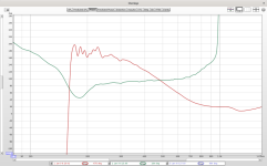
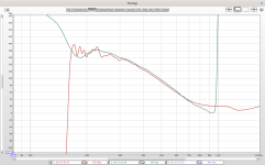
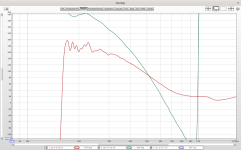
Here's an example where each will produce a nice null, but only one is reasonable to use. Cross at 500Hz, three different delays, one plot has polarity swapped and the others don't.
I would not worry too much about the tweeters power handling ability.
With DSP once you have attenuated it to match the other drivers it will probably never experience that much power during normal listening. Also with DSP can give it a third or forth order high pass to give it more protection with a few click of the mouse buttons.
In a conventional speaker the crossover components would eat up a lot of the applied musical power before it even reaches the tweeter. The music power in the higher frequencies is very much reduced, starting to tail off after 1 KHz as a rough reference point.
In all likely hood the SB tweeter you linked too is better than your current tweeter simply due to modern manufacturing techniques and the skill applied to the design of SB acoustic speakers. It should certainly have the edge in terms of its directivity due to the application of the waveguide.
Use a search of the internet and this forum to gather information on what others think of the SB tweeter, I think it has been mentioned a few times. Its paper specs look good and sensible, but I haven't tried its, and hence do not know how good it is. When you consider the cost of buying a separate tweeter and a separate waveguide, its cost doesn't seem unreasonable here in the UK is the best I can say.
SB Acoustics play safe and recommend 2nd order Xover at 2.5Khz for nearly all of their tweeters.
As a DIYer it is up to you to explore the boundary and see how you can blend it with the two woofers with a typical aim to to optimise the directivity and make it as seamless as possible, Consequently people ideally will be looking to use it below 2KHz to blend directivity and keep distortion low.
Going forward you will need to have more "Off" axis response measurements, ideally loaded to VituixCad to help you understand what is happening with the speakers and chosen DSP parameters and how they affect the overall measured frequency response and DI .
This is kind of data that is used in review channels that rely on their Klippel data to make some of the judgements on a loudspeakers capabilities. Your early data is starting to look sensible, but currently it is all related to on axis measurements.
I don't know that tweeter, but I like most sb drivers and as raymondj says its most likely an upgrade over the one you have.I would like a wg one and I was looking at wave-guided tweeters of SB Acoustics and they have two. The Satory one is nice, but it is too large and will not fit on my baffle.
The other one is this:
https://sbacoustics.com/product/sb26stwgc-4-fabric/
It is non Satory, much cheaper and will fit size wise. But I am not sure if it is intended for my kind of speaker. It has very high power handling. This makes me think it is designed for some specialised application.
Not sure how much you will really gain from such a small waveguide, probably better than no waveguide, but ideally it's size should be matched to the lowest frequency you will use the tweeter for and the midrange driver it is supposed to match.. I must admit I haven't read your thread in detail.. too busy xD
But a gross simplification regarding the waveguide is if it has the same size and shape as your midrange drivers cone then it will have a somewhat similar dispersion at whatever crossover frequency you choose. There is much more to waveguides than this of course, but it's a start 🙂
Give a look at this project by @hifijim
Assessing the tweeter:


The next step is to see if my estimates of tweeter performance are accurate. I constructed a prototype from XPS foam board, 310 mm wide, with a 20 mm bevel. I made polar frequency response scans in 15 degree increments from 0 to 180. The results are shown below.
As I had hoped, the small waveguide begins working at about 3k. Most 25 mm dome tweeters have a constant DI of about 4 dB up to around 5k, and then they steadily become more directive. This small waveguide begins controlling directivity at 3k. It is a small, but important...
@AllenB - We all try to be helpful in our own ways. For the purpose of my last post, I was trying to be as short and succinct as possible in describing a problem I had with the OP's hardware and how I solved it as opposed to writing a treatise on amplitude, phase and delay. I'll continue to limit my posts to as short and concise as I can and hope the OP gains some value in that a little bit at a time. I hope in the future you don't find that uncomfortable.
Assembly of both complete. Time to measure and program as a pair.

I’ve tried searching but can’t find this guide, can someone post a link please?I found a very useful guide here on using Hypex Filter Design, thanks to DannerD3H.
Here you go
Hello people!
It seems that many people are having trouble getting a Hypex FusionAmp set up properly. Others simply would like a clear application note.
As I did not seem to have had any issues with my method, I will share here what I did in a step-by-step instruction as an application note for a 3-way setup!
First off, I have nothing to do with Hypex. I do not know anything other than what can be found in the HFD help file or on their webpage. As such, this is no official guide, so use at your own risk! 🙂
Before we get started. Here are some useful links:
HFD software...
Null testing is a common discussion across the internet for more than it's limited scope of useful applications.For the purpose of my last post, I was trying to be as short and succinct as possible
In this case it causes a loss of information, as I wanted to point out with the example plots.
Somehow i thought the op was a beginner whose design would fit well in the category of useful applications 😀across the internet for more than it's limited scope of useful applications.
I don't follow your example plots at all. A reverse null test can tell a lot, but not if you aren't already close. I have no idea what you are trying to show there. Loss of information???? How is measuring something a loss of information.Null testing is a common discussion across the internet for more than it's limited scope of useful applications.
In this case it causes a loss of information, as I wanted to point out with the example plots.
In those three plots, phase is the same for both traces at the crossover frequency of 500Hz. This means all three would produce a good looking null at 500Hz.
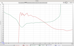
I don't need to reverse anything to prove this.. however if I use null plots I'm not able to clearly see the phase relationship in the wider crossover region. With correct polarity plots, I can.
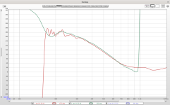
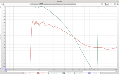
I don't need to reverse anything to prove this.. however if I use null plots I'm not able to clearly see the phase relationship in the wider crossover region. With correct polarity plots, I can.


Ok... I see one correct alignment, and two with either a positive or negative time alignment of almost 7" error, which is a lot, and beyond anything I might build.
At a glance, it's obvious that the second two are not "excellent x-overs", because the sum at 2k drops below the tweeter output at 2k. The drivers are fighting each other there.
Can you now show all three in the opposite polarity? I predict that there will be a null at 1k in all three, which was maybe your point..... but, 2k will peak slightly above the tweeter response in the second two. The null on the first will be nice and wide, and "perfect". The null on the second two will be much more narrow near the top, and probably not quite symmetrical.
The shape of the null is a poor indicator of the phase relationship and besides, natural driver variations will change the phase and levels so that the peaks/nulls may be widened or narrowed, removed or reversed. Not what you see on the simulator.and two with either a positive or negative time alignment of almost 7" error, which is a lot,
Half a wavelength is the nearest null event either way but with driver variations, you may not need even this amount of delay to see a null 😉 Here's an overlay of the above plots with reversed polarity. The null depths are the same.
Last edited:
- Home
- Loudspeakers
- Multi-Way
- 3-way to active - Hypex FA253 - learning project