That's your filter, not the one in post #40 where you altered the notch from my suggestion.
this is the result with values suggested by you
I suspect you are tired of trying my suggestions by now. It's OK if you want to stop. That woofer that you are using as a mid has really bad breakup, I didn't look at the factory files till now.
One last thing. You never tried the .3uf cap in series with the .8mH coil. That may reduce some of that breakup. You might also want to cross lower than 2k.
One last thing. You never tried the .3uf cap in series with the .8mH coil. That may reduce some of that breakup. You might also want to cross lower than 2k.

No I'm not tired of trying. Any tentative to find a better solution is ok.I suspect you are tired of trying my suggestions by now. It's OK if you want to stop. That woofer that you are using as a mid has really bad breakup, I didn't look at the factory files till now.
Playin a bit with values I have now this result.
do you mean always in the notch filter?One last thing. You never tried the .3uf cap in series with the .8mH coil. That may reduce some of that breakup.
I tried to cross around 2000Hz (as my original project).You might also want to cross lower than 2k.
Hi, just a comment: why this 1uF capacitor to ground? In high frequencies you are basically shorting the amp to ground.

it is to control the impedence and compensate the effect of the 15uF cap. If I remove it then we the impedence will decrese to less then 2 ohm between 4 and 10kHz
I would put a least a resistor in series with the 1uF. You can try 4.7ohms for example.
Something like this?
In the solution I've shown on post #76, impedance is always above 4ohms and there is no direct capacitor path to ground.
This might cause issues with your amp.
I tried to replicate you r schema but it seems based on datasheet graphs there are not similar to enclosure and diffraction simulations.
A cap in parallel with the 1.2mH coil can make a notch. Try some very small values, and observe the effect. Sometimes a notch like this is very helpful. Other times it's not a good option. The response above the notch tends to come back up, so it's a juggling act. A .3uf cap on the .8mH in the other Sims would be tuned around 10k I think. It will be lower if added across the 1.2mH. You will have two notches to play with. Could be an advantage, but who knows. Try a few common values. (.22, .33, .44uf) If it doesn't work, you will know pretty quick.No I'm not tired of trying. Any tentative to find a better solution is ok.
Playin a bit with values I have now this result.
View attachment 1451167
do you mean always in the notch filter?
I tried to cross around 2000Hz (as my original project).
View attachment 1451168
Last edited:
Oh I'm so sorry. I previously said to put the cap in series with the coil. I guess I was having a senior moment. I used the wrong word. You put it in parallel with the coil.
Last edited:
A cap in parallel with the 1.2mH coil can make a notch. Try some very small values, and observe the effect. Sometimes a notch like this is very helpful. Other times it's not a good option. The response above the notch tends to come back up, so it's a juggling act. A .3uf cap on the .8mH in the other Sims would be tuned around 10k I think. It will be lower if added across the 1.2mH. You will have two notches to play with. Could be an advantage, but who knows. Try a few common values. (.22, .33, .44uf) If it doesn't work, you will know pretty quick.
Hey, I think it is a good idea
Yes! If this meets your other requirements, I think it's better to keep this resistor.Something like this?
In terms of a flat frequency response and sensible Impedance and phase that does look nice.
A few words of caution, and maybe taking a step back and revisiting earlier steps in your post.
It is very difficult to pull off a design that has such a beautiful flat response, and at the same time sounds good. You will not know until you try, but that could be expensive in terms of design/build time, wood, component cost and being less than satisfied if it sound is less than perfect. If you had measuring equipment you possibly would be able to correct things and have a good loudspeaker.
I think one of the main issues is around the design is its overall output level and maybe how baffle step affects the midrange and tweeter too,
As far as I can see, and apologies for not asking more about it earlier, is that in post 11 there is a question about the bass driver level at 90dBs. Both Temp25 asked the question and shadowplay62 in post 19 point to the fact that in reality the bass will never be as high as the currently modelled 90dB for 1 watt input power in the low frequencies.
Yes, once built you will have room gain depending on where you position the speakers within the room. Adjusting for a new bass level will have a knock on affect in the mid and tweeter circuits as well. This may mean that their their responses could need dropping to approx. 5dB in level for the mid and approx. 7dB for the tweeter wild guesses because I do not know the baffle dimensions?
Maybe you could let us have the dimensions of the two driver cabinets 10L mid and tweeter, and 70Litre bass,
Sticking with Shadowplay62 advice for Infinite baffle seems to have a sensible 6mS group delay with a modelled f10 around 32Hz.
I think the two crossover frequencies are too close, 450 and 1800Hz roughly. And that when it is made it will not be so beautiful. I believe that without measuring the drivers in the boxes and new simulation, he should not buy parts for the crossover.
This should help the situation. I initially took for granted that your bass sim was OK. It's not. If you have included room gain, maybe it is.
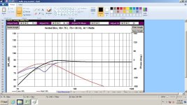
This is the woofer at 1w. Sealed, and ported shown. Ported changes nothing above 100hz.
Baffle loss is 6dB, and depending on baffle dimensions, it's about 5dB at 100hz.
So, if you sim for no BSC, you would be at 88dB for the speaker. If you sim for 4dB of BSC, you would be at 84dB for the speaker.
Unless I used the wrong data, you're not going to be even close to 90dB.
If I'm wrong, I apologize in advance.
Attachments
In a typical room, 3-4dB of baffle step correction may be sufficient. But it is still necessary to have some correction. This means that the mids and highs have to be muted by that much. It's not even bad, because he can raise the impedance a bit on the tweeter part.
I do not like steep slope but that's what I came up with: on-axis FR is a bit rugged, but off-axis, PIR and SP FR are quite decent, at least in simulation.
Baffle is 38x63cm and the woofer enclosure is a closed box of 70L (full stuffed).
Mid and tw have 4cm offset to the right.
Woofer is 17cm from the bottom.

Baffle is 38x63cm and the woofer enclosure is a closed box of 70L (full stuffed).
Mid and tw have 4cm offset to the right.
Woofer is 17cm from the bottom.
Thanks for you warning. I know, it was same story for the other speakers project. But in the end they sound good... may be not perfect, but good. Consider that even if I have a preamplifier that give me the opportunity to equalize some frequency, I usually listen with flat settings.In terms of a flat frequency response and sensible Impedance and phase that does look nice.
A few words of caution, and maybe taking a step back and revisiting earlier steps in your post.
It is very difficult to pull off a design that has such a beautiful flat response, and at the same time sounds good. You will not know until you try, but that could be expensive in terms of design/build time, wood, component cost and being less than satisfied if it sound is less than perfect. If you had measuring equipment you possibly would be able to correct things and have a good loudspeaker.
I think one of the main issues is around the design is its overall output level and maybe how baffle step affects the midrange and tweeter too,
As far as I can see, and apologies for not asking more about it earlier, is that in post 11 there is a question about the bass driver level at 90dBs. Both Temp25 asked the question and shadowplay62 in post 19 point to the fact that in reality the bass will never be as high as the currently modelled 90dB for 1 watt input power in the low frequencies.
Yes, once built you will have room gain depending on where you position the speakers within the room. Adjusting for a new bass level will have a knock on affect in the mid and tweeter circuits as well. This may mean that their their responses could need dropping to approx. 5dB in level for the mid and approx. 7dB for the tweeter wild guesses because I do not know the baffle dimensions?
Maybe you could let us have the dimensions of the two driver cabinets 10L mid and tweeter, and 70Litre bass,
Sticking with Shadowplay62 advice for Infinite baffle seems to have a sensible 6mS group delay with a modelled f10 around 32Hz.
So the cabinet should have external size heigth 63cm, width 38 cm and depth 45 cm. I would use hard plywood (or MDF) of 19mm. For the midrange and tweeter the idea is to have a "mini room" of height 24,5 cm, width 34 cm and depth of 12 cm, something like this
I was thinking the same. My idea would be increase a bit the high frequency (2000 or 2200) and lowerthe other around 300. I will try to do it soonI think the two crossover frequencies are too close, 450 and 1800Hz roughly. And that when it is made it will not be so beautiful. I believe that without measuring the drivers in the boxes and new simulation, he should not buy parts for the crossover.
Mmm, not sure I simulated BSC. What I simulated with WinISD and Vituix is the enclosure response for bass reflex with 70L and fs = 27HzThis should help the situation. I initially took for granted that your bass sim was OK. It's not. If you have included room gain, maybe it is.
This is the woofer at 1w. Sealed, and ported shown. Ported changes nothing above 100hz.
Baffle loss is 6dB, and depending on baffle dimensions, it's about 5dB at 100hz.
So, if you sim for no BSC, you would be at 88dB for the speaker. If you sim for 4dB of BSC, you would be at 84dB for the speaker.
Unless I used the wrong data, you're not going to be even close to 90dB.
If I'm wrong, I apologize in advance.
Then I simulted the diffraction.
How can I simulate the BSC?
- Home
- Loudspeakers
- Multi-Way
- 3 way project - final impedence too low