Not so goodInteresting changes for post 37. What does the frequency response look like with the two other drivers enabled with those Xover values?
Try adding a small cap in parallel with the .82mH coil.
You had the right idea on your notch. One ohm is just a good starting point. Experiment with higher values. Sometimes it gets even better.
I would look at the tweeter alone, like you did with the mid. Can you show just the raw tweeter response and the filtered tweeter response on the same graph with that software. It will help you alot to visualize what is needed.
I think I know what is needed. Alter the 3rd order on the tweeter. Hold the response flat down as low as possible, then make it turn downward sharply at 3k. This will not be quite what you need, but the knee will increase the SPL at 4k. If you look at your filter transfer right now, you can see that your filter is reducing 4k about 5dB. Need to get that up. (If possible.)
Last edited:
It does looks like it is coming together in terms of frequency response.
I like the simplification of the mid circuit, and so will your pocket in terms of not needing so many expensive Xover components.
Some further possibilities could be.
One of the difficulties here is knowing exactly how you have modelled the Bass and Midrange response in terms of the baffle diffraction.
Did you use the diffraction tool to place the drivers on a representative baffle doing that will provide a more accurate representative data which means when you build it should need some small amount of adjustment to give a good loudspeaker.
I like the simplification of the mid circuit, and so will your pocket in terms of not needing so many expensive Xover components.
Some further possibilities could be.
Change the notch frequency to move it lower, In an attempt to lower the mid driver break up amplitude.
In conjunction with the above you could reduce the tweeter input capacitor by a few values, maybe temporarily short the input resistor to the tweeter and see how a Lpad directly in front of the tweeter affects the response. if you are lucky it may work in a positive way,
If it does work but you have too much extreme treble, you can go back to re instating a RC as per your post 14.
One of the difficulties here is knowing exactly how you have modelled the Bass and Midrange response in terms of the baffle diffraction.
Did you use the diffraction tool to place the drivers on a representative baffle doing that will provide a more accurate representative data which means when you build it should need some small amount of adjustment to give a good loudspeaker.
I also think it will come together. The trick is to see why. This goes quick when doing a sim, but slows way down when posting one change per hour. The OP may have already figured it out while I was away napping. The impedance could go south, but maybe not.
Last edited:
Seems to be working well as far as the response though. This is not final. The woofer to mid handoff looks good in the sim. Real life will be different, but for now, I'm trying to help the OP work with the sim. Other issues can be addressed afterwards.
If you're not familiar with that type of notch, you'll like what adding a cap across the .82mH is going to do. I don't know the exact value, but when you add one, a huge hole shows up. Make the value smaller, and the hole moves higher in frequency. I think there will be virtually no output from the mid at 10k once the cap is added. May not be needed, but a neat tool for the toolbox. Doesn't fit every situation though. We will see.It does looks like it is coming together in terms of frequency response.
I like the simplification of the mid circuit, and so will your pocket in terms of not needing so many expensive Xover components.
Some further possibilities could be.
Change the notch frequency to move it lower, In an attempt to lower the mid driver break up amplitude.In conjunction with the above you could reduce the tweeter input capacitor by a few values, maybe temporarily short the input resistor to the tweeter and see how a Lpad directly in front of the tweeter affects the response. if you are lucky it may work in a positive way,If it does work but you have too much extreme treble, you can go back to re instating a RC as per your post 14.
One of the difficulties here is knowing exactly how you have modelled the Bass and Midrange response in terms of the baffle diffraction.
Did you use the diffraction tool to place the drivers on a representative baffle doing that will provide a more accurate representative data which means when you build it should need some small amount of adjustment to give a good loudspeaker.
Last edited:
Try adding a small cap in parallel with the .82mH coil.
You had the right idea on your notch. One ohm is just a good starting point. Experiment with higher values. Sometimes it gets even better.
mmm adding the notch there doesn't seems work. I tried several values, but the result is bad. In my schema there were also another coil after the notch.
I would look at the tweeter alone, like you did with the mid. Can you show just the raw tweeter response and the filtered tweeter response on the same graph with that software. It will help you alot to visualize what is needed.
I think I know what is needed. Alter the 3rd order on the tweeter. Hold the response flat down as low as possible, then make it turn downward sharply at 3k. This will not be quite what you need, but the knee will increase the SPL at 4k. If you look at your filter transfer right now, you can see that your filter is reducing 4k about 5dB. Need to get that up. (If possible.)
this is the response simulated with diffraction I'm using for the tweeter
it is not the filter that is reducing 5db at 4kHz. It is the diffraction.
Last edited:
Hi, try also to invert polarity between mid/tweeter. Sometimes, moving 180deg, you get a better solution.
It's just another tool in your toolbox.
It's just another tool in your toolbox.

If the distances of the driver centre from the edges of the baffle are different, you can get a better FR.mmm adding the notch there doesn't seems work. I tried several values, but the result is bad. In my schema there were also another coil after the notch.
View attachment 1450692
this is the response simulated with diffraction I'm using for the tweeter
View attachment 1450689
it is not the filter that is reducing 5db at 4kHz. It is the diffraction.
You didn't try values below 1uf. Put a .3uf in there. And get rid of the 5.6 ohm resistor.mmm adding the notch there doesn't seems work. I tried several values, but the result is bad. In my schema there were also another coil after the notch.
View attachment 1450692
this is the response simulated with diffraction I'm using for the tweeter
View attachment 1450689
it is not the filter that is reducing 5db at 4kHz. It is the diffraction.
The filter is also reducing it 5dB. Look at the red line in your filter transfer functions.mmm adding the notch there doesn't seems work. I tried several values, but the result is bad. In my schema there were also another coil after the notch.
View attachment 1450692
this is the response simulated with diffraction I'm using for the tweeter
View attachment 1450689
it is not the filter that is reducing 5db at 4kHz. It is the diffraction.
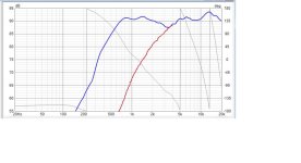
Filter the tweeter to be flat at 90dB, and -6dB at 3k. Should be doable with a 2nd, or 3rd order filter. I just did it in 2 minutes on a sim. I suspect third will sum better, but also try 2nd.
Sometimes filters don't cooperate. The impedance makes a difference.
You want to turn the raw response into something like the red response I added in Paint.
Sometimes filters don't cooperate. The impedance makes a difference.
You want to turn the raw response into something like the red response I added in Paint.
Attachments
Last edited:
I’d like to get back on this. Did you consider keeping your speakers and adding active subs to them? It is a way to success, more so than designing a 3-way from scratch. You are happy with your speakers. An active setup with separate subs could even outperform a 3-way. You’d obviously need a crossover (DSP would give the bonus of flattening n room response) and an amp, but those are not more expensive than the passive crossover stuff you’re about to buy. And saves you from building two complex enclosures. Just my 2ct.I'm evaluating 2 sub-woofer: SB26SFCL38-8 or dayton sd270a-88 (the first one to be preferred bcause it is 8 ohm).
I designed the cabninet, all SPL response and the crossover. My only problem is that the final impedence seems too low (about 2 ohm expecially at high freq) and I'm not able to adjust it. I tried with LPAD, but I'm not so familiar and I was not able to reach good result.
Can someone help me?
How did you get this risult?If the distances of the driver centre from the edges of the baffle are different, you can get a better FR.
View attachment 1450712
I'm not able to replicate it
I have not saved the DT project, but generally i set the TW at 7-8cm from the top and then I move the driver to the left/right till I get a good FR.
Consider that you have to move your mid too so you cannot go very close to the edge.
Tw (270-550mm, centre position is overlayed)

Mid (270-400mm, centre position is overlayed)

Consider that you have to move your mid too so you cannot go very close to the edge.
Tw (270-550mm, centre position is overlayed)
Mid (270-400mm, centre position is overlayed)
Filter the tweeter to be flat at 90dB, and -6dB at 3k. Should be doable with a 2nd, or 3rd order filter. I just did it in 2 minutes on a sim. I suspect third will sum better, but also try 2nd.
Sometimes filters don't cooperate. The impedance makes a difference.
You want to turn the raw response into something like the red response I added in Paint.
something like this?
the impedence is still low...
in any case with this configuration, enabling the mid and woofer I obtain this result
I think we are using different .frd files, because at the same XY i have different results.I have not saved the DT project, but generally i set the TW at 7-8cm from the top and then I move the driver to the left/right till I get a good FR.
Consider that you have to move your mid too so you cannot go very close to the edge.
Tw (270-550mm, centre position is overlayed)
View attachment 1450893
Mid (270-400mm, centre position is overlayed)
View attachment 1450891
Your tweeter cap is too large (15 uF) and the coil too small (180 uH).the impedence is still low...
That essentially shorts a lot of energy and reduces impedance to unusable levels.
You could start with standard filter calculator values to avoid this error.
You could also put the resistor before the shunt coil.
Last edited:
- Home
- Loudspeakers
- Multi-Way
- 3 way project - final impedence too low