For a quick introduction have a look at these. They are not exactly up to date due to the software evolving over time, but the steps work in the same way.
You have come this far I think even if you have to replay them a few times, you will quickly get the idea. You have your own data, or shadowplay62 data to load up as the initial on axis , 0 degree file.
You have come this far I think even if you have to replay them a few times, you will quickly get the idea. You have your own data, or shadowplay62 data to load up as the initial on axis , 0 degree file.

There's 6dB between 4π and 2π radiation. But 'room gain' (the contribution of reflections from boundaries to the sound pressure level at any point in space) has to be accounted for. For any typical situation in a normal listening environment BSC can't be simulated easily.How can I simulate the BSC?
Ahh basically I missed to merge the enclosure response with the diffraction.For a quick introduction have a look at these. They are not exactly up to date due to the software evolving over time, but the steps work in the same way.
You have come this far I think even if you have to replay them a few times, you will quickly get the idea. You have your own data, or shadowplay62 data to load up as the initial on axis , 0 degree file.
So fixing the woofer response I can obtain:
It looks good.
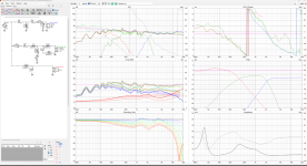
I do not like steep slope but that's what I came up with: on-axis FR is a bit rugged, but off-axis, PIR and SP FR are quite decent, at least in simulation.
Baffle is 38x63cm and the woofer enclosure is a closed box of 70L (full stuffed).
Mid and tw have 4cm offset to the right.
Woofer is 17cm from the bottom.
View attachment 1451321
I also tried the version suggested by you and also this one seems quite good.
You have greatly reduced the impedance on the bass section. That's not good at all. Increase inductance, decrease capacitance
Re the data Post 103.
How about letting VituixCAD export the data. Make sure you have the correct driver selected when you do it.
It will generate 0-180 degrees in 10 degree intervals for Horizontal and Vertical measurements which is a lot more simulated data which ultimately should lead to a better build.
I usually take measurement's which in general means that I don't have to worry about ultra accurate simulations. However, if you cannot do this it makes sense to use the tools as much as possible. 0-180 degree data allows the directivity index and power to be correctly modelled.
Somebody is also bound to mention the fact that there is no driver position x, y and z in the current data. I am not 100% sure about this bit myself when using horizontally offset drivers so as to obtain the flattest frequency response.
I expect others to jump in or I may read up on this and post something tomorrow.
The relative positioning of the mid and tweeter can have a pronounced effect due to the smaller wavelengths involved at these frequencies and there are some rules of thumb about having them less than a 1/4 wavelength apart at the Xover frequency, but also a value of 1.2 the wavelength can help If I remember correctly. Hifijim and others have discussed that in his design threads
Good luck with the continuing design.
Last edited:
You have greatly reduced the impedance on the bass section. That's not good at all. Increase inductance, decrease capacitance
it is not so easy to change values there... increasing the coil and reducing the cap generates a hole around 200Hz.
In any case below a tentative
Generate the LF part in the enclosure tool and export itHow can I simulate the BSC?
Generate the diffraction resp. at 10m/1m in the diffraction tool and export them
Generate the HF part (full space at 1m) in the diffraction tool; check the Directivity option if you wanna simulate off-axis responses and export them
Load all the FR in the merger tool and export them
Repeat the same procedure for the midrange
Generate off-axis FR for the tw and export them
thanks all for your suggestion.
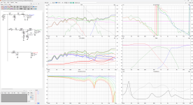
After yours input about the woofer enclosure and diffraction simulation I lowered a bit the resonant frequency to 28Hz reducing the SPL at 50 Hz to 88db.
This is the final result

I moved the lower crossover around 350 Hz and then the tweeter crossover around 2400Hz.
Do you think that this is a good result?
After yours input about the woofer enclosure and diffraction simulation I lowered a bit the resonant frequency to 28Hz reducing the SPL at 50 Hz to 88db.
This is the final result
I moved the lower crossover around 350 Hz and then the tweeter crossover around 2400Hz.
Do you think that this is a good result?
I think it would be very interesting to see your latest crossover modelled by Shadowplay62 so we could compare the two.
I have tried to do it myself but as it is my first attempt with the merge tool I think I am probably going wrong there. Plus I have a suspicion that I have placed the mid 5mm in error. Consequently I cannot say this is good data.
I have tried to do it myself but as it is my first attempt with the merge tool I think I am probably going wrong there. Plus I have a suspicion that I have placed the mid 5mm in error. Consequently I cannot say this is good data.
Attachments
I do not like steep slope but that's what I came up with: on-axis FR is a bit rugged, but off-axis, PIR and SP FR are quite decent, at least in simulation.
Baffle is 38x63cm and the woofer enclosure is a closed box of 70L (full stuffed).
Mid and tw have 4cm offset to the right.
Woofer is 17cm from the bottom.
View attachment 1451321
Can you please share more precise position for the 3 drivers?
I understood that the woofer is at x=190 mm y=170 mm. Am I right?
what about the mid and tweeter?
Shodowplay62's post earlier in the thread gave suggestions.
What I aimed to used in the diffraction calculator were the following:
Bass width 190, height 185, and SD 210
Mid 230, 420 and SD 118 and I imported a ZMA file representative of the mid in a 10 Litre sealed Cabinet
Tweeter 230, 565. SD 6.2
I have a feeling I was out by 5mm though on my mid height, and i haven't had time to retrace my steps or do some further verification on merging things correctly.
I had to do chores and clean the windows.
Ok thanks@ggerla
Measuring from the bottom:
X - Y
T: 230 - 550
M: 230 - 400
W: 190 - 170
W-M ctc distance is 230mm, so keep the Fc between W and M at 380Hz or as close as possible.
T-M ctc distance is 150mm, so keep the Fc between T and M at 2200Hz or as close as possible.
I have just one doubt... the distance between the outer circle of woofer and mid on Y axis is less then 19 mm. Inside the cabinet I need to create the room for the mid and tweeter...
Is this ok?
I think there will need to be some modifications if it doesn't fit your mid compartment dimensions.
Ideally you want an internal 45 degree chamfer for the midrange. So this should be factored in to get the midwoofer snug in its new home.
I think from the various posts and your own Xover iterations you should be able to re specify the cabinet dimensions slightly to allow everything to fit. nicely and re model.
maybe its a good idea in future to look at the Baffle step for all drivers, and don't worry about a perfectly flat response. Maybe revisit the simplest Xover iteration and see what you can now achieve.
If you haven't already visited it would be sensible to look at Troels Gravesen loudspeaker site which has lots of information on cabinet building and driver routing.
If it makes things easier regarding a new layout, because of the low Xover frequencies involved between the mid and Woofer you can have a greater separation between the two. Maybe its more of a balance of visual aesthetics rather than acoustics.
If in doubt you can always change the Y position in the simulation and see how it affects things, or not.
If in doubt you can always change the Y position in the simulation and see how it affects things, or not.
You need to consider the diameter of the holes (145 and 230mm). The drivers should fit well. You can increase the M-W ctc distance to 24cm moving the woofer down by 1cm: there will be a slight change in the vertical directivity: I tried to increase the distance in my simulation and I did not see any differences.Ok thanks
I have just one doubt... the distance between the outer circle of woofer and mid on Y axis is less then 19 mm. Inside the cabinet I need to create the room for the mid and tweeter...
View attachment 1451731
Is this ok?
@shadowplay62 thanks a lot!
may be my last question...
in the low pass filter for the woofer, there is a cap of 120uF. It is a must to use a film capacitor or considering that it is in parallel I can use an electrolytic non-polarized cap?
May be I already know the answer, but before spent 50€ per cap I think it is better ask 🙂
Have a look at the price of a decent Mundorf Ecap or similar polar type capacitor for audio at the correct voltage level.. You can upgrade down the line, you may want to tweak things in the build, therefore personally I would stay away from exotic caps in the woofer circuit.
- Home
- Loudspeakers
- Multi-Way
- 3 way project - final impedence too low