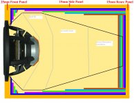
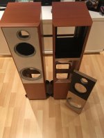
NB: on the chamfer image, I didn't adjust the layout of the dampening material but in real life the dampening material would be laid over the chamfer 🙂
Damping sheets and insulation perform 2 different tasks. Damping is a treatment for reducing cabinet panel resonances (very specific in frequency) so that they don't vibrate essentially like a drum head. Insulation is intended to absorb as much of the internal sound energy as possible to 1) reduce the the amount of sound transmission through the cabinets (a wide band of frequencies) and 2) to reduce the amount of sound energy that might be reflected back from inside the chamber and back out through the cone.
Now in truth there is a little crossover in functions here, since the insulation absorbs more internal energy so that there is less available to excite the panel resonances and likewise, by layering the walls with the a soft heavy layer some sound energy is also absorbed, but each is really best at its own individual task so I wouldn't substitute 15mm of bitumen sheets for some quality insulation especially at the back of the cabinet which is the primary reflecting surface back to the driver.
The chamfer I was referring to is a 45 degree chamfer of the back side of the driver cutout. See the 1st image attached which would be the absolute ideal done with a CNC machine but a router and a 45 degree chamfering bit gets you pretty close.
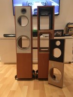
Image 2 is just a quick idea of what I had in mind when I suggested a reverse cone rear chamber. The black lines would show about the extent of the contouring with damping sheets that I would go for. And it's a lot and that's why I was thinking of a cheaper diy solution and also I don't know if you actually even have that much extra cabinet volume to play with. Note that the lines start right at the edge of the driver which is where the 45 degree chamfer starts. The other lines give you a rough idea of what I would do with insulation. Don't forget, 3 dimensions, not just 2.
Now if you don't have that much extra volume to play with, then maybe don't worry too much about the reverse cone idea as it may use up too much space. Maybe instead, just go with a minimum of 15mm of damping on the mid chamber's side and top panels (the complete panels) and then see how much you have left over for the bottom and back panels.
Now in truth there is a little crossover in functions here, since the insulation absorbs more internal energy so that there is less available to excite the panel resonances and likewise, by layering the walls with the a soft heavy layer some sound energy is also absorbed, but each is really best at its own individual task so I wouldn't substitute 15mm of bitumen sheets for some quality insulation especially at the back of the cabinet which is the primary reflecting surface back to the driver.
The chamfer I was referring to is a 45 degree chamfer of the back side of the driver cutout. See the 1st image attached which would be the absolute ideal done with a CNC machine but a router and a 45 degree chamfering bit gets you pretty close.
Image 2 is just a quick idea of what I had in mind when I suggested a reverse cone rear chamber. The black lines would show about the extent of the contouring with damping sheets that I would go for. And it's a lot and that's why I was thinking of a cheaper diy solution and also I don't know if you actually even have that much extra cabinet volume to play with. Note that the lines start right at the edge of the driver which is where the 45 degree chamfer starts. The other lines give you a rough idea of what I would do with insulation. Don't forget, 3 dimensions, not just 2.
Now if you don't have that much extra volume to play with, then maybe don't worry too much about the reverse cone idea as it may use up too much space. Maybe instead, just go with a minimum of 15mm of damping on the mid chamber's side and top panels (the complete panels) and then see how much you have left over for the bottom and back panels.
Attachments
Ok, thank you for explaining.
Chamfer makes sense and I should be able to achieve at least some Chamfer'ing even if its not 45 degrees.
Volume wise, it will be a bit of a compromise however again I think i'll be able to get close to the inverted cone shape. The verticle brace is 15mm deep, so I think i'll have to go 20mm deep with the dampening sheets over that area but again the cone shape will help me achieve that 🙂
I'm still a little unclear on the insulation. Are you suggesting Insulation + dampening on the rear panel? i.e. Insulation glued to the back panel and then dampening over the top?
45 degrees is best but how much wood you need to take out depends on the thickness of the front baffle and/or the thickness of the front driver flange plus the depth of both the surround and the cone profile - what you are trying to do is give the rear sound coming from the cone unimpeded egress away from the driver. Your woofer for eg might have a thicker flange and perhaps a larger surround so the cone starts deeper in the horizontal plane and so may only need a little bit of wood removed or perhaps none at all.
Sorry if I wasn't clear: damping sheets glued to the panels, insulation inside the remaining space in the cabinet.
I was considering your mid chamber when looking at it from the side today and realized a simple little change in the panel separating the mid and the woofer could help save you both some internal volume and some damping material. The sides would remain about the same as I pictured above but if you can put that bottom panel in at an angle, that might help you out. See the rough sketch attached.
Perhaps a little steeper angle than what I drew would be better but I don't have your exact mid chamber dimensions and I just kind of winged the diagram. That's actually a lot of material up at the top, so you can perhaps see how sneaking a couple of layers of 15mm wood in there would keep the costs down.
I guess it all depends if you can physically get those kinds of cuts done and into the existing cabinet.
I was also reconsidering the need for any vertical bracing extending into the mid chamber and figure you can get away without it.
Attachments
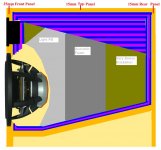
Yes, just looking at the diagram again, a steeper angle on the bottom panel and a shallower angle on the top damping sheets will help to both use less volume in the mid chamber and less damping sheets.
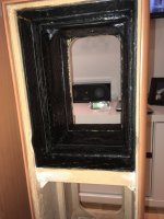
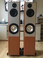
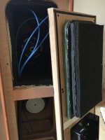
Good progress made since my last post. Front panels and drivers fitted. Mid/Tweeter enclosure dampening finished off.
Rear panel dampening is a combination of: Fiberboard, Bitchem pads, high density closed cell foam and then open acoustic cell foam. Internally the mid/tweeter enclosure has BAF wadding.
Currently running the drivers in and hope to have 20-30 hours on them by the weekend, ready for some measurements 🙂
Attachments
Particularly satisfying to get the cabinet done and the drivers in and ready to go, isn't it?
Now that has the potential to sound very good indeed.
Now that has the potential to sound very good indeed.
Particularly satisfying to get the cabinet done and the drivers in and ready to go, isn't it?
Now that has the potential to sound very good indeed.
Yes, very much so. Also a big sense of achievement and relief that all those man-hours have come together nicely 🙂
Looking forward to taking measurements this weekend 🙂
Hi spark,
2) the Peerless looks good in about 19-20L tuned somewhere around 35Hz with a port about 2" x 9.5".
(Remember these are net volumes - the total volume minus bracing, driver volume, port volume, xo volume, etc.)
Hi jReave,
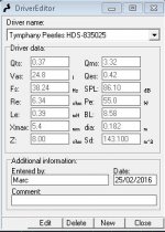
I'm currently going over the woofer enclosure design and wanted to just double check the above numbers with you.
WinISD is giving me different numbers. The port size numbers it's producing look way off but i'm not sure where i'm going wrong? The driver data I have for the Peerless look to be ok in WinISD.
Enclosure volume: 18.6L
Tuning Fr 41.78Hz
Port Diameter: 4"
Port length: 26.25"
Attachments
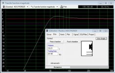
You don't really want to be using a port over 2 feet in length. 😱
Play around with the program some more. Vary the port diameter and see what happens to port length and port air velocity. Port resonance is affected too but I don't think WinISD shows that.
I haven't used WinISD in a while since I prefer Unibox, but I think you may need to use the pro version to do what I'm going to suggest next.
Next, you want to be looking at port air speed at the maximum SPL you are going to be using the speakers at. So change the power input (in the "Signal" tab?) and look at xmax with an eye to keeping cone movement below xmax right down to about 20Hz since you want to use them for movies without a sub. Now go back and look at port air speed at your max SPL and see how small you can get the port diameter while keeping the port air velocity below about 25m/s.
And I might start off with a slightly lower tuning on the port, or in other words start off with the port at maximum length and then you can cut it shorter if you want to tune it just a bit higher.
You don't really want to be using a port over 2 feet in length. 😱
Play around with the program some more. Vary the port diameter and see what happens to port length and port air velocity. Port resonance is affected too but I don't think WinISD shows that.
I haven't used WinISD in a while since I prefer Unibox, but I think you may need to use the pro version to do what I'm going to suggest next.
Next, you want to be looking at port air speed at the maximum SPL you are going to be using the speakers at. So change the power input (in the "Signal" tab?) and look at xmax with an eye to keeping cone movement below xmax right down to about 20Hz since you want to use them for movies without a sub. Now go back and look at port air speed at your max SPL and see how small you can get the port diameter while keeping the port air velocity below about 25m/s.
And I might start off with a slightly lower tuning on the port, or in other words start off with the port at maximum length and then you can cut it shorter if you want to tune it just a bit higher.
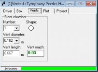
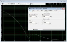
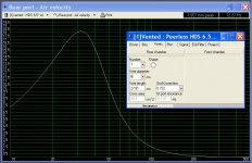
I'm sure I've got something wrong but here are my vent size results.
Vol: 18.21L
Dia: 2.76"
Len: 8.82"
Fb: 48.21hz
Ven Mach Peak: 17.666m/s
Max System Input: 45W
I'm finding the signal input power and the XMax graph confusing. As soon as the input power increases the lower frequencies shoot past XMax.
Attachments
You're doing everything right, but I think that maybe what you are just not quite putting together is that you don't really need a lot of power for the driver to play loudly.
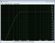
Look at the SPL graph too. At 1W, you get about 87dB at 1 m. That's actually pretty loud. You said that you don't intend to play too loudly so I suspect you will probably be happy between about 80 and 85dB at your listening position so if you can get about 90dB @ 1m per driver I think you'll be fine.
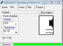
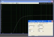
So let's look at the graphs again with:
Vb = 18.2L
Fb = 38Hz
P dia = 4cm
P length = 11.39cm
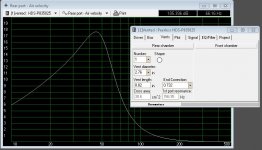
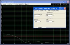
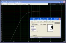
So 1st you should see that the lower tuning gets rid of the peaking @ 65Hz and lowers both F3 and F6 and is designed to avoid booming or 1-note bass once you let the room do its thing too. Working with 4W, you get about 93dB @ 1m and keep xmax happy right down to about 20Hz. Port velocity with a 4cm diameter port peaks with ~ 33Hz content at about 14.5m/sec. So in reality the port could actually still be a little smaller.
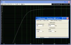
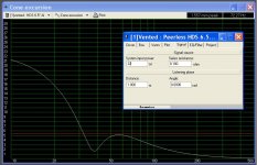
But, maybe you want to play the speakers louder on occasion with just music, so with content above ~ 40Hz. So the last 3 graphs are with 32W which gets you about 102dB @ 1m (too loud for an apartment in my opinion) and keeps cone excursion below xmax for content above ~33Hz but port speed gets a little too high unless you increase diameter to ~ 6cm which keeps it below 18.5m/sec.
Notice of course that the larger diameter port will still be fine with lower frequency content at 4W, so it's up to you to figure out what's going to work best for you here. But in reality, you often have to deal with the port diameters that you have access to. Plumbing pipe (PVC or ABS) is very frequently used in diy but it only comes in certain sizes. A 2" diameter might just about be perfect for your application here if you can find it nearby. I like to get one of the 90* elbows too, attach the 1st part securely to the cabinet and then be able to pull the 2nd length out of the elbow to cut it down to a shorter length if I think that sounds better.
Look at the SPL graph too. At 1W, you get about 87dB at 1 m. That's actually pretty loud. You said that you don't intend to play too loudly so I suspect you will probably be happy between about 80 and 85dB at your listening position so if you can get about 90dB @ 1m per driver I think you'll be fine.
So let's look at the graphs again with:
Vb = 18.2L
Fb = 38Hz
P dia = 4cm
P length = 11.39cm
So 1st you should see that the lower tuning gets rid of the peaking @ 65Hz and lowers both F3 and F6 and is designed to avoid booming or 1-note bass once you let the room do its thing too. Working with 4W, you get about 93dB @ 1m and keep xmax happy right down to about 20Hz. Port velocity with a 4cm diameter port peaks with ~ 33Hz content at about 14.5m/sec. So in reality the port could actually still be a little smaller.
But, maybe you want to play the speakers louder on occasion with just music, so with content above ~ 40Hz. So the last 3 graphs are with 32W which gets you about 102dB @ 1m (too loud for an apartment in my opinion) and keeps cone excursion below xmax for content above ~33Hz but port speed gets a little too high unless you increase diameter to ~ 6cm which keeps it below 18.5m/sec.
Notice of course that the larger diameter port will still be fine with lower frequency content at 4W, so it's up to you to figure out what's going to work best for you here. But in reality, you often have to deal with the port diameters that you have access to. Plumbing pipe (PVC or ABS) is very frequently used in diy but it only comes in certain sizes. A 2" diameter might just about be perfect for your application here if you can find it nearby. I like to get one of the 90* elbows too, attach the 1st part securely to the cabinet and then be able to pull the 2nd length out of the elbow to cut it down to a shorter length if I think that sounds better.
Attachments

Thank you. I get where I was going wrong now. You have a good memory, I don't need very high volumes, so the lower value of 93dB is fine. My listening distance is around 3m, so with the dB drop over that distance that's loud enough for me.
The local electronics store stocks 4cm tubes, so i'll grab a couple of those this week 🙂
Bass Reflex Tube 40.5mm | Maplin
I like the elbow idea, that's a nice trick! I try with a straight tube to start with and see where that gets me. The tubes and very inexpensive.
The local electronics store stocks 4cm tubes, so i'll grab a couple of those this week 🙂
Bass Reflex Tube 40.5mm | Maplin
I like the elbow idea, that's a nice trick! I try with a straight tube to start with and see where that gets me. The tubes and very inexpensive.

I'll just note that Unibox suggests just a slightly longer port with a 4cm diameter, 13-14cm, so you might try this to start off with and cut it shorter if you want a little more output from the port.
I'll just note that Unibox suggests just a slightly longer port with a 4cm diameter, 13-14cm, so you might try this to start off with and cut it shorter if you want a little more output from the port.
The off-the-shelf port I had in mind is only 12cm long. So I might have to start off with that and then add a cm or two from a donor pipe 🙂 Solvent cement should be perfect for that.
Ok so I've made the measurements at last 🙂
Think I've done this correctly. Both Near and Far Field REW Mdat'ss attached. Do the FR's look reasonable/correct?
Measurements (zipped):
https://drive.google.com/file/d/0Bwwef9FGi6GicGVILVhQdFB0OGc/view?usp=sharing
When google drive appears, choose the download icon (top right)
Think I've done this correctly. Both Near and Far Field REW Mdat'ss attached. Do the FR's look reasonable/correct?
Measurements (zipped):
https://drive.google.com/file/d/0Bwwef9FGi6GicGVILVhQdFB0OGc/view?usp=sharing
When google drive appears, choose the download icon (top right)
After smoothing and proper gating, your measurements show a strong correlation with my simmed FR's. Very nice.
However, you do not need a nearfield measurement of the tweeter nor measurements below 20Hz for the mid or woofer.
Next you'll need to go over near and farfield splicing in Response Blender and also take some additional measurements for finding the driver acoustic offsets. See Bagby's papers on those topics for further info.
Thanks. Good to hear that its looking ok so far 🙂
I've been reading the Response Blender tutorial but its not clean what constites...?
High Frequency Response FRD data
Low Frequency Response FRD data
I only have the REW files and also exports of them as FRD's.
I've been reading the Response Blender tutorial but its not clean what constites...?
High Frequency Response FRD data
Low Frequency Response FRD data
I only have the REW files and also exports of them as FRD's.
- Status
- Not open for further replies.
- Home
- Loudspeakers
- Multi-Way
- 3-Way Build Project - Woofer help