Thinking some more, I realise that you are probably referring to the glue at the joins separating the damping layer. This is a "break of the continuity" but it is a fraction of a millimeter after clamping tightly. Furthermore the glue join is damped by the silicone on either side. I did not consider this glue a significant bridge between inner and outer box. I did consider using the silicone as a glue for all the joints, which would have maintained the continuity, but rejected this on the grounds of overall box integrity. I wanted the inner box to be as stiff as possible by using a strong polyurethane glue.4) I am curious on a construction detail: The various parts of the box - the "walls" of it - were cut at 90 degrees at their four edges. When joining them, to form the speaker box, there would be a break of the continuity of the damping material between the "inner" and the "outer" MDF box at the joining edges. How did you treat this matter?
Thanks. Details......
Thank you so much, Bon, for your response.
1) First of all, in order to understand your technics, I tried to extend the small sketch (MS word file) you attached, by drawing one more wall, vertical to the upper and lower ones, making it the way I consider correct. Please see the attached file and let me know if I am correct or not (I am not so good in MS paint, but the basic idea can be shown).
2) As far as the Bostic V60 Silicone, I understand that I need to search for a silicone, made for glazing glasses. I believe the one I found seems to be similar to the Bostik V60.
http://www.bison.net/static/products/assets/asset_5037_3.pdf
3) Regarding cork sheet. Apparently, you have not tested its bouncing properties. Neither have I - I admit. But, because it is much easier to work with (I feel that shearing will not be a big problem), I will also test it against the silicone and perhaps some other materials. When I have the test results, I will open a separate thread, perhaps, on the right category (subwoofers). If it behaves well, it might be even cheaper than silicone.
Panagiotis
P.S.:
It seems that when I tried to modify your MS word file, by inserting the small additional sketch, which I drew in MS Paint, something went wrong and your initial "stepped" up and down wall sections do not show as such ("stepped"). However, I was not able to bring them back to your initial schematic. Please, consider them in my file the way they are in yours.
-
Attachments
Last edited:
I have attached my own modified sketch below.1) First of all, in order to understand your technics, I tried to extend the small sketch (MS word file) you attached, by drawing one more wall, vertical to the upper and lower ones, making it the way I consider correct. Please see the attached file and let me know if I am correct or not (I am not so good in MS paint, but the basic idea can be shown).
This URL will not open for me.2) As far as the Bostic V60 Silicone, I understand that I need to search for a silicone, made for glazing glasses. I believe the one I found seems to be similar to the Bostik V60.
http://www.bison.net/static/products/assets/asset_5037_3.pdf
You must understand that constrained layer damping WORKS by transferring the transverse deflection of the panel into a shearing strain in the damping layer, where the energy is dissipated as heat. Cork does not shear significantly and will be ineffective as a damping layer in a constrained mode panel. The bounce test is a measure of the effectiveness of the constraining layer but other properties can affect the result, unrelated to the constrained layer. For example, substituting plywood for mdf, the ball energy is significantly absorbed by permanent deformation of the top ply layers. A more refined test would be needed to determine the effectiveness for such materials.3) Regarding cork sheet. Apparently, you have not tested its bouncing properties. Neither have I - I admit. But, because it is much easier to work with (I feel that shearing will not be a big problem), I will also test it against the silicone and perhaps some other materials. When I have the test results, I will open a separate thread, perhaps, on the right category (subwoofers). If it behaves well, it might be even cheaper than silicone.
Attachments
Some thoughts...
Thanks a lot, Bon. Actually this is what I meant in my sketch. Fully understood!
Strange. Please, try:
Welcome - Bison
then, click on "Products"
then, click on "Sealants"
At the right place of the page, you will see a small picture titled: "Silicone Glass". Click on it and the product page opens.
At the right place of the new page, you will see under "DOWNLOADS" a link of a PDF file, named "Technical Documentation". Click on it and the specs of this product appear.
First of all, you are 100% right, when saying that the energy is dissipated as heat into the mass of the damping material. However, your test method - excellent, as a basic idea - with all other parameters remaining the same, shows the difference of the damping effectiveness between the various materials. Certainly, I understand that a more refined test would be required for more accurate results (I believe that a series of instruments are also required for such a test), but someone can have an idea about the differences between materials.
I am going to discuss the whole matter with the other friends of the group and put down some more thoughts and I will revert.
Thank you again.
Panagiotis
-
I have attached my own modified sketch below.
Thanks a lot, Bon. Actually this is what I meant in my sketch. Fully understood!
This URL will not open for me.
Strange. Please, try:
Welcome - Bison
then, click on "Products"
then, click on "Sealants"
At the right place of the page, you will see a small picture titled: "Silicone Glass". Click on it and the product page opens.
At the right place of the new page, you will see under "DOWNLOADS" a link of a PDF file, named "Technical Documentation". Click on it and the specs of this product appear.
You must understand that constrained layer damping WORKS by transferring the transverse deflection of the panel into a shearing strain in the damping layer, where the energy is dissipated as heat. Cork does not shear significantly and will be ineffective as a damping layer in a constrained mode panel. The bounce test is a measure of the effectiveness of the constraining layer but other properties can affect the result, unrelated to the constrained layer. For example, substituting plywood for mdf, the ball energy is significantly absorbed by permanent deformation of the top ply layers. A more refined test would be needed to determine the effectiveness for such materials.
First of all, you are 100% right, when saying that the energy is dissipated as heat into the mass of the damping material. However, your test method - excellent, as a basic idea - with all other parameters remaining the same, shows the difference of the damping effectiveness between the various materials. Certainly, I understand that a more refined test would be required for more accurate results (I believe that a series of instruments are also required for such a test), but someone can have an idea about the differences between materials.
I am going to discuss the whole matter with the other friends of the group and put down some more thoughts and I will revert.
Thank you again.
Panagiotis
-
Yes, I found it. The specs seem well suited to a damping layer, especially elasticity and filling capacity. Watch out for the skin over time though. Panels have to be fitted and securely clamped within the skin over time. At least two people definitely required, unless you come up with a faster way of applying the silicone than the standard gun. Make up a test panel, say 300 x 300 mm, leave to cure for a week. Then try and separate the layers. Remember that the silicone is required to hold frameless glass in an aquarium. The water pressure load on a glass panel is considerable. I have no idea why the mould resistance is nil or even if it matters in this application.Strange. Please, try:
Welcome - Bison
then, click on "Products"
then, click on "Sealants"
At the right place of the page, you will see a small picture titled: "Silicone Glass". Click on it and the product page opens.
At the right place of the new page, you will see under "DOWNLOADS" a link of a PDF file, named "Technical Documentation". Click on it and the specs of this product appear.
PRODUCT DESCRIPTION
High quality, permanently elastic, water resistant silicone sealant for glass
applications.
CURE TIMES
Skin over time: approx. 15 minutes
* Curing time may vary depending on a.o. surface, product quantity used, humidity
level and ambient temperature.
TECHNICAL PROPERTIES
Water resistance: Very good
Temperature resistance: -50°C to +150°C
UV resistance: Very good
Mould resistance: Nil
Chemicals resistance: Very good
Paintability: Not paintable
Elasticity: Very Good
Filling capacity: Very good
Good luck and have fun.Certainly, I understand that a more refined test would be required for more accurate results (I believe that a series of instruments are also required for such a test), but someone can have an idea about the differences between materials.
I am going to discuss the whole matter with the other friends of the group and put down some more thoughts and I will revert.
... what has been done will be done again
; there is nothing new under the sun. Ecclesiastes 1:9
To my utter astonishment, while following a link to the AudioTechnology Gallery diy page, I found a photo of a project which is externally virtually identical to mine.
GALLERY
I am amazed that we have both independently arrived at almost identical designs for the reduction of diffraction effects. I assume the builder was also very influenced by the 1950 AES paper of Harry F. Olson, “Direct Radiator Loudspeaker Enclosures ”. The saying form follows function seems entirely appropriate here. I have attempted to contact the builder and alert him to this thread with an invitation to compare construction techniques.
I'm still shaking my head when I think of the number of iterations I considered before settling on the final shape.
Funny how that happens, I have unique idea after unique idea only to find someone has already invented that wheel.
Pity I cant search for the idea I'm about to have before I have it and save myself the trouble of inventing it.
Pity I cant search for the idea I'm about to have before I have it and save myself the trouble of inventing it.
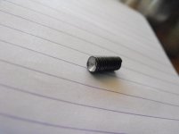
I managed to clean out the two tight bolt holes with a 5 mm tap inserted from the rear with the woofers removed. I cleaned out all the other holes the same way as a precaution. The broken bolt required a bit of effort. It broke off before emerging from the steel plate. My plan was to drill it out with a smaller bit, 4.5 mm, and re-tap. I had no real expectation of a result because the bolt is hardened. With not much room to spare, my 10.8 V battery Bosch drill just allowed me to insert the bit from the rear in contact with the bolt end. Pulling towards me and trying to keep straight, I quickly blunted 2 of my 3 titanium 4.5 mm bits. With the last bit, I seemed to be getting through, when suddenly the broken bolt stub shot out of the hole into my lap! The drill bit had lined up perfectly had somehow got a purchase to the bolt end and screwed it out of the steel plate. What are the odds? I knew no one would believe me so I took photos. All the bolts are now back in clean holes.But then there is Murphy and his Law. Three of the woofer have one bolt that has the same issue. Because the baffle has a 3 mm layer of damping, occasionally a bolt passing through, picks up silicone that then jams the thread into the steel backing plate. I feared something like this and tried to clear out each thread with a lubricated trial long bolt. This worked 29 times out of 32 but the 3 failures are causing me grief. The first failure happened with a jam on the withdrawal. It was solid. I succeeded in snapping the hardened bolt in the thread. The other 2 jammed on the way in and I backed off straightaway. So now 3 woofers are one bolt shy. I will try and clean out the threads of two with a thread tapper but I will have to drill out the snapped off bolt and re-tap with possibly a larger thread.
I will report on the sound after some more serious listening. So far I am a very happy diy-er.
Attachments

Last edited:
What are the chances of that happening? Guess when you are drilling close to size of the bolt you have a fair amount of purchase on the bolt, so not overly surprising, but you take your wins where you find them 🙂
Pretty amazing what heat and vibration will do for a stuck bolt.
Glad you got them all cleaned up, I'd like to read your impressions of the sound. When your ready. This has been an interesting project to follow along with.
John
Glad you got them all cleaned up, I'd like to read your impressions of the sound. When your ready. This has been an interesting project to follow along with.
John
Early impressions
I've been holding back on commenting on the sound because reviews are very subjective. Furthermore, there is still a bit of tweaking to do. However, by a substantial margin, these are the best speakers I have listened to in my home or any other domestic situation. Firstly let me state that I like accurate bass and I know how it should sound since I play electric bass. In most of my favourite music, the bass should be just THERE, not necessarily drawing attention to itself but providing support for everything else. Just as in a live performance. What I am finding is that the bass on well known recordings, is more detailed and subtle than I have previously noticed. I put this down to the combination of twin woofers allowing for less excursion and distortion, smaller 10" cones with the same motor as the 12" giving faster transients, the constrained layer damping, massive baffle, bracing and steel plate, reducing the level of enclosure "talk" resulting in cleaner bass. I pretty much expected this. I am surprised though, by the big improvement in mid-range clarity. The Scanspeak mid really does deliver on detail without any apparent harshness. I previously preferred poly cones for mid, finding most previous paper coned mids tending to be harsh, especially at higher volumes. The treble just sounds well balanced. Of course all these comments are for the crossover set to my preference. I will post a picture of the RTA frequency response at the seated listening position later. Overall, the system now sounds dynamic and detailed without harshness. I am now able to follow any instrumental part without straining or fatigue. The common response is of hearing stuff previously un-noticed and admired performers now appear much more talented and subtle than before, which can't be bad.
One thing I noticed, is the mid-range does not hide shortcoming in the mid power amps. I had to reject a number of my power amps with very good specs. The Scanspeak mid is very transparent. I will almost certainly be looking for a new mid-range amp, possibly mono-blocs. I have some mono-blocs on loan which sound very good, but run hot (the first 100 watts in class A).
The angled baffle of the mid-tweeter enclosure, is to reduce deleterious diffraction artefacts. In my well damped room with appropriate recording, this allows very wide, stable stereo imaging. It is laughably easy to show off stable outside-the-speaker stereo. I have had very good feedback from a handful of experienced listeners.
BTW, the spiked stands did improve bass tightness. The mid-tweeter enclosure sits on Sorbothane hemispheres to isolate from any bass enclosure vibration.
I got lucky with the bolt.Pretty amazing what heat and vibration will do for a stuck bolt.
Glad you got them all cleaned up, I'd like to read your impressions of the sound. When your ready. This has been an interesting project to follow along with.
John
I've been holding back on commenting on the sound because reviews are very subjective. Furthermore, there is still a bit of tweaking to do. However, by a substantial margin, these are the best speakers I have listened to in my home or any other domestic situation. Firstly let me state that I like accurate bass and I know how it should sound since I play electric bass. In most of my favourite music, the bass should be just THERE, not necessarily drawing attention to itself but providing support for everything else. Just as in a live performance. What I am finding is that the bass on well known recordings, is more detailed and subtle than I have previously noticed. I put this down to the combination of twin woofers allowing for less excursion and distortion, smaller 10" cones with the same motor as the 12" giving faster transients, the constrained layer damping, massive baffle, bracing and steel plate, reducing the level of enclosure "talk" resulting in cleaner bass. I pretty much expected this. I am surprised though, by the big improvement in mid-range clarity. The Scanspeak mid really does deliver on detail without any apparent harshness. I previously preferred poly cones for mid, finding most previous paper coned mids tending to be harsh, especially at higher volumes. The treble just sounds well balanced. Of course all these comments are for the crossover set to my preference. I will post a picture of the RTA frequency response at the seated listening position later. Overall, the system now sounds dynamic and detailed without harshness. I am now able to follow any instrumental part without straining or fatigue. The common response is of hearing stuff previously un-noticed and admired performers now appear much more talented and subtle than before, which can't be bad.
One thing I noticed, is the mid-range does not hide shortcoming in the mid power amps. I had to reject a number of my power amps with very good specs. The Scanspeak mid is very transparent. I will almost certainly be looking for a new mid-range amp, possibly mono-blocs. I have some mono-blocs on loan which sound very good, but run hot (the first 100 watts in class A).
The angled baffle of the mid-tweeter enclosure, is to reduce deleterious diffraction artefacts. In my well damped room with appropriate recording, this allows very wide, stable stereo imaging. It is laughably easy to show off stable outside-the-speaker stereo. I have had very good feedback from a handful of experienced listeners.
BTW, the spiked stands did improve bass tightness. The mid-tweeter enclosure sits on Sorbothane hemispheres to isolate from any bass enclosure vibration.
Sounds like you have made some great progress in terms of music reproduction. Likewise I am finding details in recordings I have never heard before. For me though I think it is more about the ability to better identify the sound of the instrument that is playing the notes, than it is uncovering additional detail. For example a lot of Pink Floyd songs start and end with a wind sound blowing, I am now finding that it is sounding less like the wind, and more like an instrument playing a wind sound. The additional detail makes the sound cleaner and easier to identify.
Bon,
I was just directed to your wonderful build thread. All I can say is "WOW"!.
Like your signature line implies, "excess" appears to have succeeded for you. That is nothing short of an awesome build. Well done Sir.
Bob (fellow audio looney)
I was just directed to your wonderful build thread. All I can say is "WOW"!.
Like your signature line implies, "excess" appears to have succeeded for you. That is nothing short of an awesome build. Well done Sir.
Bob (fellow audio looney)
Bon
I think I remember you saying that you're a fan of Bessel filter alignments. Could you explain why? I've been listening with my DCX on 4th order Bessel for the last few weeks and want to know what your subjective impression is, before I give you mine.
I think I remember you saying that you're a fan of Bessel filter alignments. Could you explain why? I've been listening with my DCX on 4th order Bessel for the last few weeks and want to know what your subjective impression is, before I give you mine.
Sorry, just found it. I notice a better description of the acoustic space and better soundstage depth..Bon
I think I remember you saying that you're a fan of Bessel filter alignments. Could you explain why? I've been listening with my DCX on 4th order Bessel for the last few weeks and want to know what your subjective impression is, before I give you mine.
Yes, that is part of what I hear too. I try my utmost to time and phase align my drivers. I don't rely on the DCX2496 auto align, but on old school nulling of reversed phase drivers at crossover. With the Bessel alignment I find transients to be most realistic and outside-the-speaker effects most solid and unmistakeable. I have a number of recordings that throw a wonderfully wide soundstage, way outside the speakers while keeping central images perfectly focussed. These are among the first to be played after crossover alignment. If these sound right, I am happy that everything is good. One warning though. The Bessel alignment initial roll-off rate is less steep than the equivalent L-R so drivers see more of the out of band signal i.e. there is more overlap. So your drivers have to be well behaved for a wider margin than the nominal passband. So the tweeter will potentially handle more mid-band energy and mid will handle more bass energy. As a precaution I keep the mid/tweeter crossover point relatively high (2.3-2.5 kHz). I have never found this to be a real problem. I routinely switch off the woofers and listen to the mid+treble for problems.Sorry, just found it. I notice a better description of the acoustic space and better soundstage depth.
Thanks Bob. It's good to get near the end of a build without feeling that maybe you could have tried a little bit harder. That could change after a while though 😀Bon,
I was just directed to your wonderful build thread. All I can say is "WOW"!.
Like your signature line implies, "excess" appears to have succeeded for you. That is nothing short of an awesome build. Well done Sir.
Bob (fellow audio looney)
I have a number of recordings that throw a wonderfully wide soundstage.......... If these sound right, I am happy that everything is good.
It's good to get near the end of a build without feeling that maybe you could have tried a little bit harder.
May I beg for a small list of such recordings? Please? 😉
I have yet to learn the fine art of being content with the build I have created. Inevitably, as I'm wrapping things up, the doubts of how I *could have* done things better begin to creep into my mind.
It may be the sickness we have, it may be the level of "anal retentiveness" some of us have, or it may even be the lack of confidence some of us have.
Either way, I tip my hat to you Sir. I can say that I can't think of anything you "could have", or "should have" done in this build.
Bob
I will post a list on this thread soonMay I beg for a small list of such recordings? Please? 😉
I really wish it were otherwise, but my preferred format is vinyl, where to get a great result, "everything" you do matters. I do have DVD A and SACD available but they still are not up to my vinyl front end. I wish I knew who put the "anal" in analog.It may be the sickness we have, it may be the level of "anal retentiveness" some of us have
Cross-over tuning update.
Here are some observations on the tuning and tweaking of the crossover that has been taking place over the past couple of months.
My driver choice for each speaker is Peerless Woofer P830452 (2), Scanspeak Mid-Woofer Revelator 18W8531G00, Scanspeak Tweeter D2905-970000.
I use a Behringer ECM8000 measurement microphone, Behringer DSP8024 Ultracurve Pro RTA, HFN/RR Test Disc III, Behringer DCX2496 Ultra-drive Pro.
My preferred choice of cross-over type is Bessel 24 dB/octave.
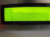
Firstly I did some pink noise FR of the unequalised individual drivers, measured at the listening position, about 3 m, height 1 m. My first surprise was how flat and extended the Peerless P830452 woofers are in-room. They pretty well matched the published graphs, with some obvious room modes added. The unequalised Scanspeak 18W8531G00 and D2905-970000 were very flat on on the listening axis. My initial crossover points are 160 Hz and 2.5 kHz. With precise level matching and reversed phase nulling, I determined the tweeter and woofer delay relative to the mid-range. The in-phase drivers are level matched for a smooth, flat overall frequency response. One issue with Bessel alignment is the more gradual initial fall-off in the stop band and less flatness in the pass band. This shows in the composite frequency response as slight broad depression around the crossover points. I fill this in with a low-Q bandpass filter for excellent overall flatness. There are a few room modes to deal with. My room dimensions give prominent axial modes at 26, 51, 70, 102 and a strong tangential mode at 37 Hz. The most audible is the 102 Hz mode, which I flatten with a sharp bandpass filter in the DCX.
Further listening with known recordings, is concerned with fine tuning the relative levels of the drivers. This is a subjective aspect. Level changes of 0.5 dB over a driver pass-band are quite audible but barely register on a RTA. The final frequency response at the listening position, is quite smooth and flat.
I experimented with the bass-mid x-over frequency. I found that as I went lower than 160 Hz, the sound became more dry and clinical although the FR at the listening position did not appear to change much. I put this down to the differing radiation patterns of the 6.5” mid and the 10” woofers. Due to their differing physical position and acoustic properties, they drive the room quite differently in the comparison range 80-160 Hz. My preference at the moment is for the 160 Hz crossover but I will experiment with a gradual lowering over the next few weeks.
I put excellent diffraction control and precise time alignment as two of my main goals and I consider that I have achieved this. My favourite recordings for wide-imaging are better than previously experienced. Some are downright distracting, with extreme right and left images in addition to locked in central images. The remaining tweaking of driver levels and x-over points is primarily to adjust the tonality but I feel I am close to a final set-up.
In the attached FR at the listening position, you can clearly see the room modes centred at 25, 50 100 Hz. This is after some attempt at smoothing them out.
Here are some observations on the tuning and tweaking of the crossover that has been taking place over the past couple of months.
My driver choice for each speaker is Peerless Woofer P830452 (2), Scanspeak Mid-Woofer Revelator 18W8531G00, Scanspeak Tweeter D2905-970000.
I use a Behringer ECM8000 measurement microphone, Behringer DSP8024 Ultracurve Pro RTA, HFN/RR Test Disc III, Behringer DCX2496 Ultra-drive Pro.
My preferred choice of cross-over type is Bessel 24 dB/octave.
Firstly I did some pink noise FR of the unequalised individual drivers, measured at the listening position, about 3 m, height 1 m. My first surprise was how flat and extended the Peerless P830452 woofers are in-room. They pretty well matched the published graphs, with some obvious room modes added. The unequalised Scanspeak 18W8531G00 and D2905-970000 were very flat on on the listening axis. My initial crossover points are 160 Hz and 2.5 kHz. With precise level matching and reversed phase nulling, I determined the tweeter and woofer delay relative to the mid-range. The in-phase drivers are level matched for a smooth, flat overall frequency response. One issue with Bessel alignment is the more gradual initial fall-off in the stop band and less flatness in the pass band. This shows in the composite frequency response as slight broad depression around the crossover points. I fill this in with a low-Q bandpass filter for excellent overall flatness. There are a few room modes to deal with. My room dimensions give prominent axial modes at 26, 51, 70, 102 and a strong tangential mode at 37 Hz. The most audible is the 102 Hz mode, which I flatten with a sharp bandpass filter in the DCX.
Further listening with known recordings, is concerned with fine tuning the relative levels of the drivers. This is a subjective aspect. Level changes of 0.5 dB over a driver pass-band are quite audible but barely register on a RTA. The final frequency response at the listening position, is quite smooth and flat.
I experimented with the bass-mid x-over frequency. I found that as I went lower than 160 Hz, the sound became more dry and clinical although the FR at the listening position did not appear to change much. I put this down to the differing radiation patterns of the 6.5” mid and the 10” woofers. Due to their differing physical position and acoustic properties, they drive the room quite differently in the comparison range 80-160 Hz. My preference at the moment is for the 160 Hz crossover but I will experiment with a gradual lowering over the next few weeks.
I put excellent diffraction control and precise time alignment as two of my main goals and I consider that I have achieved this. My favourite recordings for wide-imaging are better than previously experienced. Some are downright distracting, with extreme right and left images in addition to locked in central images. The remaining tweaking of driver levels and x-over points is primarily to adjust the tonality but I feel I am close to a final set-up.
In the attached FR at the listening position, you can clearly see the room modes centred at 25, 50 100 Hz. This is after some attempt at smoothing them out.
Attachments
- Status
- Not open for further replies.
- Home
- Loudspeakers
- Multi-Way
- 3-way active, time aligned, constrained layer construction