Try and find a copy of a Technical Note by Rane Acoustics. It is intended for pro audio but it gives a really clear set up procedure for phase alignment of drivers at the listening position. It is a good starting place. My set up procedure is a modified version but the principle is the same. In short, for each enclosure, play a sine wave at the chosen x-over frequency, set the mid and treble levels separately to be as close to identical as measured with a measurement mic at the listening position. With the sine applied to both drivers, reverse the phase of one driver and adjust the phase and delay until the mic reading bottoms out. I can easily get a 30-40 dB null. With a little practice this can be improved.
Then put the drivers back in phase. They should now be time aligned. With only two driver active the level should rise 3 dB over one driver. Reversing the drivers and repeating the level should drop 30-40 dB. Play pink noise and observe the frequency response. It should be smooth and flat through the x-over region. With one driver reversed, there should be a deep notch in the frequency response at the x-over frequency. In practice, it is at least a couple of hours work. Wear ear protection.
Yes, the DCX2496 allows delay adjustment increments of 1 mS (2 mm). I find the best null require this level of adjustment.
Would I be correct in assuming this would only work when you have a sealed box with two drivers? or would it work with an open baffle?
You are correct that my procedure is only applicable to an enclosure which only effectively radiates in a forward direction. Given what I understand about OB speakers, there is as much sound radiated rearwards as forward, with associated delays, reflections, diffraction and whatever, so the question of time alignment and phase coherence seems irrelevant for OB speakers. I must admit to having zero experience with OB speakers.Would I be correct in assuming this would only work when you have a sealed box with two drivers? or would it work with an open baffle?
I just got it! You mean the speaker to chair distance, right? I'm just very deaf in one earLooks like you made them with a predetermined listening distance in mind..
 (and a bit slow sometimes)
Try and find a copy of a Technical Note by Rane Acoustics. It is intended for pro audio but it gives a really clear set up procedure for phase alignment of drivers at the listening position. It is a good starting place. My set up procedure is a modified version but the principle is the same. In short, for each enclosure, play a sine wave at the chosen x-over frequency, set the mid and treble levels separately to be as close to identical as measured with a measurement mic at the listening position. With the sine applied to both drivers, reverse the phase of one driver and adjust the phase and delay until the mic reading bottoms out. I can easily get a 30-40 dB null. With a little practice this can be improved.
Then put the drivers back in phase. They should now be time aligned. With only two driver active the level should rise 3 dB over one driver. Reversing the drivers and repeating the level should drop 30-40 dB. Play pink noise and observe the frequency response. It should be smooth and flat through the x-over region. With one driver reversed, there should be a deep notch in the frequency response at the x-over frequency. In practice, it is at least a couple of hours work. Wear ear protection.
Yes, the DCX2496 allows delay adjustment increments of 1 mS (2 mm). I find the best null require this level of adjustment.
Just a slight correction here. Since your technique guarantees you very good phase allignment you will see a full 6dB of gain at the crossover frequency. 3dB would come if the units were 90 degrees apart.
David
Hi Dave. Yes, thanks for correcting that.Just a slight correction here. Since your technique guarantees you very good phase allignment you will see a full 6dB of gain at the crossover frequency. 3dB would come if the units were 90 degrees apart.
David
Yes. The further away you get, the higher your ears are relative to the tweeter and midrange axis. If you get far enough back, the tweeter and midrange will be aimed at you crotch. But that would probably only happen in a gymnasium sized room. Tilting back the entire speaker would make the mid tweet plane more perpendicular to the floor, eliminating distance constraints..I just got it! You mean the speaker to chair distance, right? I'm just very deaf in one ear
Last edited:
It took me years of reading to find out the information that is available on the Rane site. Thanks so much for the link. I recommend it to anyone thinking of going active. It's a great relief to read that my conclusions about the Bessel crossover topology are supported by the Rane analysis. For exampleI love "Rane notes". Very informative. Tons of info. I know the LR section by heart..
Library
A Bessel Filter Crossover, and Its Relation to Others
"Summary
It is seen that a Bessel crossover designed as described above is not radically different from other common types, particularly compared to the Linkwitz-Riley. It does not maintain linear phase response at higher frequencies, but has the most linear phase of the three discussed, along with fairly good magnitude flatness and minimal lobing for the even orders. It is one good choice when the drivers used have a wide enough range to support the wider crossover region, and when good transient behaviour is desired."
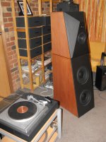
I thought you were referring to the chair being right next to the speaker and at 90 degrees to the driver axis but maybe you a referring to the mid-tweeter baffle plane. It is vertical, although in many of the images it does look to be inclined forward. This is an optical illusion caused by the woofer baffle being inclined backward at about 12.5 degrees. When the mid-tweeter are phase aligned, the main lobe should be directly forward (assuming ideal free space conditions of course)Yes. The further away you get, the higher your ears are relative to the tweeter and midrange axis. If you get far enough back, the tweeter and midrange will be aimed at you crotch. But that would probably only happen in a gymnasium sized room. Tilting back the entire speaker would make the mid tweet plane more perpendicular to the floor, eliminating distance constraints..
Aha! optical Illusion! Now it makes sense..I thought you were referring to the chair being right next to the speaker and at 90 degrees to the driver axis but maybe you a referring to the mid-tweeter baffle plane. It is vertical, although in many of the images it does look to be inclined forward. This is an optical illusion caused by the woofer baffle being inclined backward at about 12.5 degrees. When the mid-tweeter are phase aligned, the main lobe should be directly forward (assuming ideal free space conditions of course)
Stuffed and loaded
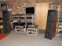
The last lap was definitely the slowest. I made up my own binding post from acrylic I got CNC'd locally and amplifier terminals I found on the web. Cost me $24 a set. Because the plate is clear acrylic, it does not hide the timber finish. I had to be especially neat with the holes. The drivers fit very well. They were close before painting and five coats of flat black made them fit even better. But then there is Murphy and his Law. Three of the woofer have one bolt that has the same issue. Because the baffle has a 3 mm layer of damping, occasionally a bolt passing through, picks up silicone that then jams the thread into the steel backing plate. I feared something like this and tried to clear out each thread with a lubricated trial long bolt. This worked 29 times out of 32 but the 3 failures are causing me grief. The first failure happened with a jam on the withdrawal. It was solid. I succeeded in snapping the hardened bolt in the thread. The other 2 jammed on the way in and I backed off straightaway. So now 3 woofers are one bolt shy. I will try and clean out the threads of two with a thread tapper but I will have to drill out the snapped off bolt and re-tap with possibly a larger thread. Apart from this glitch, i am very pleased with the look. I did not have the time to even try a rough and ready tune since we had guests over the weekend.
The last lap was definitely the slowest. I made up my own binding post from acrylic I got CNC'd locally and amplifier terminals I found on the web. Cost me $24 a set. Because the plate is clear acrylic, it does not hide the timber finish. I had to be especially neat with the holes. The drivers fit very well. They were close before painting and five coats of flat black made them fit even better. But then there is Murphy and his Law. Three of the woofer have one bolt that has the same issue. Because the baffle has a 3 mm layer of damping, occasionally a bolt passing through, picks up silicone that then jams the thread into the steel backing plate. I feared something like this and tried to clear out each thread with a lubricated trial long bolt. This worked 29 times out of 32 but the 3 failures are causing me grief. The first failure happened with a jam on the withdrawal. It was solid. I succeeded in snapping the hardened bolt in the thread. The other 2 jammed on the way in and I backed off straightaway. So now 3 woofers are one bolt shy. I will try and clean out the threads of two with a thread tapper but I will have to drill out the snapped off bolt and re-tap with possibly a larger thread. Apart from this glitch, i am very pleased with the look. I did not have the time to even try a rough and ready tune since we had guests over the weekend.
Attachments
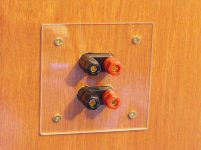
Because the plate is clear acrylic, it does not hide the timber finish.
But it could quite easily if you masked off a tiny section around the terminal and gave them a coat of black.
Nice job! the finished result is quite pleasing to the eye.
Do you plan to put any feet on it?
Stands
I quite like viewing the timber even though the holes are not perfect. I have in the past painted black the rear side of the acrylic. The result is a high gloss black. A bit like 3 mm of gloss clear coat. I might do this laterBut it could quite easily if you masked off a tiny section around the terminal and gave them a coat of black.
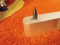
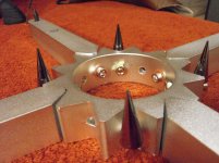
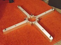
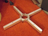
I found some solid aluminium stands and added extra spikes to handle the weight. I level them on a perfectly flat surface. The raisr the speakers about 50 mm. I won't install them until I have finished moving them around. I can't say they slide well on carpet. 150 kg sinks into the pile and underlay too much for that. I can tug them into place without too much trouble.B
Do you plan to put any feet on it?
Attachments
I took a long time to think about what I wanted to achieve. I'm known to be slow to gee up but unstoppable once I get going.And that is why they turned out so good, no detail is too small or was overlooked
I hope I am not infringing any rules by posting the site where I got them.Did you buy the stands locally?
E&T 55X1 Adjustable Single Stand for Amps,Speakers Etc. | eBay
The shipping was expensive but they are very heavy.
Those stands are so cool! I gotta get me some..I quite like viewing the timber even though the holes are not perfect. I have in the past painted black the rear side of the acrylic. The result is a high gloss black. A bit like 3 mm of gloss clear coat. I might do this later
I found some solid aluminium stands and added extra spikes to handle the weight. I level them on a perfectly flat surface. The raisr the speakers about 50 mm. I won't install them until I have finished moving them around. I can't say they slide well on carpet. 150 kg sinks into the pile and underlay too much for that. I can tug them into place without too much trouble.
Here is another company with some good ideas(The cones are included)
Products Soundocity Audio Equipment Speaker Stabilizing Outriggers with Spikes
Last edited:
Absolutely brilliant work!
Those bases will be a great finishing touch.
We'll have to fix this
Those bases will be a great finishing touch.
I don't get the same buzz out of building electronics
We'll have to fix this
Amazing Work! Some questions....
Hats off for your work, Bon. It's really admirable!
Myself and some friends have recently gathered together to discuss a serious project for building a subwoofer (lots of subwoofers, actually, one or more for each one of us ) and I followed this thread from the beginning to the end.
I have some questions, mainly focused on the constrained layer construction principle and the materials and method you used for your construction. Here they are:
1) You mention the Bostik V60 Silicone as the damping material between the two main MDF layers. I believe that any silicone rubber adhesive with similar characteristics (specs) would do the job. I say this, because it is not possible (or very easy) to find an Australian made silicone in Europe. Am I right or not?
2) You described a testing method, which led you to finally choose the Bostik V60. I understand that the steel ball was dropped on a pre-made "sandwich" of two MDF sheets and the damping material between them. In this case, the actual test was made on the final construction, i.e. on all three layers been put together and not on the damping material itself, right?
3) What is your opinion about cork sheet of 4 or 5 or 6 mm, as a damping material?
4) I am curious on a construction detail: The various parts of the box - the "walls" of it - were cut at 90 degrees at their four edges. When joining them, to form the speaker box, there would be a break of the continuity of the damping material between the "inner" and the "outer" MDF box at the joining edges. How did you treat this matter?
(I would understand that, in order to retain the continuity of the damping material, a 45 degrees cut of the edges would do the job, but again I understand that joining two edges with a 45 degrees cut is not an easy job and it certainly gives a weak joint. This is why I ask this last question).
Thanks in advance.
Panagiotis
-
Hats off for your work, Bon. It's really admirable!
Myself and some friends have recently gathered together to discuss a serious project for building a subwoofer (lots of subwoofers, actually, one or more for each one of us
) and I followed this thread from the beginning to the end.I have some questions, mainly focused on the constrained layer construction principle and the materials and method you used for your construction. Here they are:
1) You mention the Bostik V60 Silicone as the damping material between the two main MDF layers. I believe that any silicone rubber adhesive with similar characteristics (specs) would do the job. I say this, because it is not possible (or very easy) to find an Australian made silicone in Europe. Am I right or not?
2) You described a testing method, which led you to finally choose the Bostik V60. I understand that the steel ball was dropped on a pre-made "sandwich" of two MDF sheets and the damping material between them. In this case, the actual test was made on the final construction, i.e. on all three layers been put together and not on the damping material itself, right?
3) What is your opinion about cork sheet of 4 or 5 or 6 mm, as a damping material?
4) I am curious on a construction detail: The various parts of the box - the "walls" of it - were cut at 90 degrees at their four edges. When joining them, to form the speaker box, there would be a break of the continuity of the damping material between the "inner" and the "outer" MDF box at the joining edges. How did you treat this matter?
(I would understand that, in order to retain the continuity of the damping material, a 45 degrees cut of the edges would do the job, but again I understand that joining two edges with a 45 degrees cut is not an easy job and it certainly gives a weak joint. This is why I ask this last question).
Thanks in advance.
Panagiotis
-
Last edited:
The Bostik V60 is specifically designed for glazing of large glass panels. It has a high adhesive property even under extreme deformation.1) You mention the Bostik V60 Silicone as the damping material between the two main MDF layers. I believe that any silicone rubber adhesive with similar characteristics (specs) would do the job. I say this, because it is not possible (or very easy) to find an Australian made silicone in Europe. Am I right or not?
Bostik Australia :Industry - Catalogue - Bostik V60
I do not think you can assume any silicone would have suitable properties. I would advise testing for adhesion, curing, damping effectiveness, neutral curing. The black also makes for easier visual alignment for cutting.
Yes. I dropped a 20 mm steel ball from about 1 m height. If you can take high speed videos, and average 10 readings for each construction, it will save time.2) You described a testing method, which led you to finally choose the Bostik V60. I understand that the steel ball was dropped on a pre-made "sandwich" of two MDF sheets and the damping material between them. In this case, the actual test was made on the final construction, i.e. on all three layers been put together and not on the damping material itself, right?
Cork is a good damping material in the correct application. It is not suitable for constrained mode damping, which requires the damping material to shear readily3) What is your opinion about cork sheet of 4 or 5 or 6 mm, as a damping material?
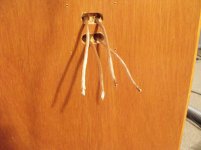
The attached pdf shows adjacent panels. You can see that the inner panels are separated by the damping layer at each join. The outer layers are separated from each adjacent outer layer, but the final marine ply layer joins them together.4) I am curious on a construction detail: The various parts of the box - the "walls" of it - were cut at 90 degrees at their four edges. When joining them, to form the speaker box, there would be a break of the continuity of the damping material between the "inner" and the "outer" MDF box at the joining edges. How did you treat this matter?
I rejected the 45 degree join for all the reasons you mentioned. The rebate join, if accurately done, results in three glue surfaces 18 mm wide, at right angles. It is much easier to align the panels with the 90 degree rebate joins. I would have had to use battens to strengthen and seal the joins if using 45 degree joins. I do agree that it is easier to make a single 45 degree than three 90 degree cuts, of precise depth.(I would understand that, in order to retain the continuity of the damping material, a 45 degrees cut of the edges would do the job, but again I understand that joining two edges with a 45 degrees cut is not an easy job and it certainly gives a weak joint. This is why I ask this last question).
-[/QUOTE]
Attachments
Last edited:
- Status
- This old topic is closed. If you want to reopen this topic, contact a moderator using the "Report Post" button.
- Home
- Loudspeakers
- Multi-Way
- 3-way active, time aligned, constrained layer construction