
Aestethicaly speaking the world became so awefull than I will not take my third Pfizer shoot...
That one is good perhaps if living in a batcave without light.
I prefer that if the subject is not about design researches : Great Balls of Prestige , per ScottG input.
Notice the mid has a WG, I assume a Volt unit, the proac being discontinued. The treble unit could be bafles is usefull as well for instance if passive for a better delay.
Last edited:

Haha. Noverber has arrived, but let's not fall into despair. There is still beauty in the world and I'm still optimistic that I can eventually get good results with the current approach. Meaning Q100 drivers and a strongly shaped front baffle crafted using 3-axis CNC, 3D printing and laser cutting. Just don't expect fast results.
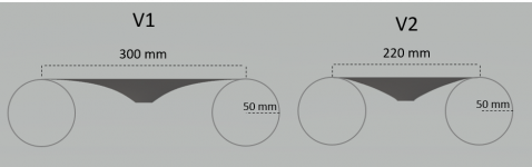
The first waveguide was mainly designed based on infinite baffle simulations so it's not a surprise that it's not working optimally together with a real baffle. The next step is to use a narrower waveguide which allows use of large rounding without making the baffle very wide. Here's a sketch.

I think V2 may very well be as good as V1 in terms of directivity. V1 just occupies too much space on the baffle in comparison with the depth and waveguiding effect. V1 is very flat around the perimeter anyway.
V1->V2------->This could of course be extrapolated to a case with a minimal flare around the driver and even larger rounding radius, which in a circular symmetric case would be the Ikea Blanda bowl which was suggested. On the other hand, Heissmann showed that diffraction can be controlled nicely also in a baffle which is shaped only on the side edges. And Dutch&Dutch 8C* does a good job without using very exotic shapes. I think in both of these cases the waveguide and baffle have been optimized together in order to achieve the smooth polar response. I suppose instead of minimizing diffraction I attempt to get controlled diffraction since that's what the WG does, and the baffle edges can provide a bit of additional directivity without messing the response if designed carefully. I have just taken the first small steps on this path.
*I'm referring to the tweeter+WG part here, not the cardioid bass.
I didn't have time to build a baffle for testing it during the weekend. This is actually my next task.
The first waveguide was mainly designed based on infinite baffle simulations so it's not a surprise that it's not working optimally together with a real baffle. The next step is to use a narrower waveguide which allows use of large rounding without making the baffle very wide. Here's a sketch.
I think V2 may very well be as good as V1 in terms of directivity. V1 just occupies too much space on the baffle in comparison with the depth and waveguiding effect. V1 is very flat around the perimeter anyway.
V1->V2------->This could of course be extrapolated to a case with a minimal flare around the driver and even larger rounding radius, which in a circular symmetric case would be the Ikea Blanda bowl which was suggested. On the other hand, Heissmann showed that diffraction can be controlled nicely also in a baffle which is shaped only on the side edges. And Dutch&Dutch 8C* does a good job without using very exotic shapes. I think in both of these cases the waveguide and baffle have been optimized together in order to achieve the smooth polar response. I suppose instead of minimizing diffraction I attempt to get controlled diffraction since that's what the WG does, and the baffle edges can provide a bit of additional directivity without messing the response if designed carefully. I have just taken the first small steps on this path.
*I'm referring to the tweeter+WG part here, not the cardioid bass.
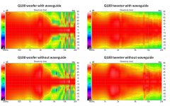
..what's it like with baffle and no waveguide?
I didn't have time to build a baffle for testing it during the weekend. This is actually my next task.
Attachments
Last edited:

..what's it like with baffle and no waveguide?
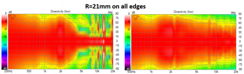
Here you go. Both on the same baffle as previously. R=21mm rounding on all edges. Looks like the baffle diffraction has even bigger impact for the 2kHz range without the waveguide. Also the higher frequencies are tidier with than without. So this waveguide seems to have some beneficial effects, but the response is dominated by the baffle. Let's see if the second iteration brings improvements in that respect.
Attachments
😎 
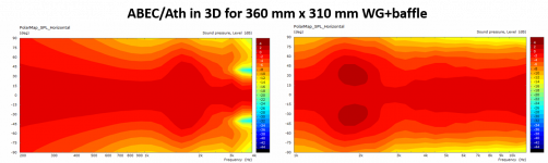
It looks like it could use a wider *baffle profile to get the tweeter's low-freq. "bloom" (around 1.5 kHz) pushed further down to accommodate the woofer's slight lack of pressure (..around that 1 kHz region).
*including waveguide.
It looks like it could use a wider *baffle profile to get the tweeter's low-freq. "bloom" (around 1.5 kHz) pushed further down to accommodate the woofer's slight lack of pressure (..around that 1 kHz region).
*including waveguide.
Is there a ratio for the baffle width to make the frequency spectra to pop even?
Like, optimal wavelength to the edge from 500hz to 20 000..
Is this "directivity index"?
And is there a build out there that shows how this should look?
Low end will be hard i suspect but up stairs?
Maybe this is something on the way to what i mean? (image)
Strauss SE-NF-3 ~80k usd / pair 😀
Like, optimal wavelength to the edge from 500hz to 20 000..
Is this "directivity index"?
And is there a build out there that shows how this should look?
Low end will be hard i suspect
but up stairs?Maybe this is something on the way to what i mean? (image)
Strauss SE-NF-3 ~80k usd / pair 😀
Attachments
😎
It looks like it could use a wider *baffle profile to get the tweeter's low-freq. "bloom" (around 1.5 kHz) pushed further down to accommodate the woofer's slight lack of pressure (..around that 1 kHz region).
*including waveguide.
Hmm. I thought that the narrowing and bloom would move together if the baffle width is changed. I'm going to consider the wider baffle as an option, but the next iteration is going to be in the other direction. Meaning a narrower baffle which moves the diffraction to shorter wavelength where it is more easily managed with edge rounding. So reducing the bloom and pushing it towards the frequencies where the woofer starts to beam and using the narrowing as an additional low frequency directivity. Then crossing at ~2.5kHz and playing with XO slopes.
Last edited:
A wider baffle moves the diffraction signature (or "bloom") LOWER in freq..
Narrowing it will move that 1.5-1.7 kHz tweeter signature upward in freq.. (..and of course do the same to the woofer's - though for the woofer that's to a point because of the woofer's narrowing directivity at higher freq.s beyond 2.4 kHz).
Narrowing it will move that 1.5-1.7 kHz tweeter signature upward in freq.. (..and of course do the same to the woofer's - though for the woofer that's to a point because of the woofer's narrowing directivity at higher freq.s beyond 2.4 kHz).
If interested, here are some larger quarter-round's for cabinets (..there probably is something like this in Europe, but I haven't searched for it.):
MDF CABINET CORNERS
MDF CABINET CORNERS
Hmm. I thought that the narrowing and bloom would move together if the baffle width is changed. I'm going to consider the wider baffle as an option, but the next iteration is going to be in the other direction. Meaning a narrower baffle which moves the diffraction to shorter wavelength where it is more easily managed with edge rounding. So reducing the bloom and pushing it towards the frequencies where the woofer starts to beam and using the narrowing as an additional low frequency directivity. Then crossing at ~2.5kHz and playing with XO slopes.
Yeah the trick is to have a transducer "beam" so that most of the sound radiates forward and little radiates to sides to travel along the baffle to the edge and to diffract and cause the interference seen as bloom on the normalized polar map. The beaming is natural for direct radiators and waveguides on frequencies that are (roughly) shorter in wavelength than the size of the transducer / waveguide. This defines the upper limit of frequency bandwidth where the diffraction interference occurs.
Then there is the baffle that extends beyond the "beaming", the transducer, which projects some of the sound forward if it is significantly large relative to the wavelenghts, which means the baffle is relatively big obstacle for (roughly) shorter waveleghts than the baffle size and diffraction occurs. The baffle size kind of defines the lower limit of frequency bandwidth where the diffraction interference happens.
So to minimize diffraction interference the trick is to minimize this bandwidth where diffraction occurs, or remove the edge to prevent diffraction, or cancel the sound at the edge.
Minimization of the bandwidth can be done by bringing the limits closer together. Upper limit is defined by the transducer size, which has to be there and we can do nothing about it, but the baffle can be minimized by removing it altogether or by making it as small as possible one way or another like adding the roundovers, which is kind of removing the edge as well (for wavelengths that are small relative to the roundover). Cancellation could perhaps be done with cardioid system I suspect, along with minimization of the baffle. All three effects are seen with the D&D 8c for example.
In case of coaxial driver the tweeter has quite a long distance to the edge because the woofer is there so best bet is to try manipulate the waveguide part as well as you can to affect the beaming as much as possible, eg. control the tweete response forward not to the edge. roundover right at the woofers edge might work best but eventually it is the woofer cone profile, the part of the waveguide you cannot change that will make or break the performance in this respect I think. You can play some with the crossover frequency and possibly get the almost inevitable diffraction positioned nicely somewhere there in between. Specialty here is that the woofer being bigger transducer beams lower in frequency and thus has different upper limit for diffraction than the tweeter. But, you still should mind about the directivity of the whole system.
I'm sure you can minimize the diffraction interference and get as good system as possible but not sure if diffraction could be avoided completely. Maybe with a sphere as enclosure, but that defines the system directivity control as well.
Actually it is very hard to imagine a multiway system that doesn't diffract at some point so minimizing is best one can achieve I think. The freestanding ATH examples mabat has been rolling out have least diffraction and most control I've seen but they are only the treble. Add in a woofer somewhere nearby and bam, back to diffraction land. Altgough potentially at very low frequency, below 1kHz.
Hopefully here was some food for thought. If you can imagine further and develop very low diffraction system without significant drawbacks, please post it 🙂 I think there is a sweet spot to be found and if you manage to find it and get some rule of thumb generated out of it, that would be really nice info for coaxial builders!
Last edited:
Quick thought on the logic, since the tweeter is necessarily having the woofer as its surround the baffle edge roundover should be approximately r of the woofer to significantly reduce the diffraction of the tweeter signal, at the baffle edge. At the same time the roundover would mitigate diffraction of the woofer nicely. Anything less (no baffle for example) would mitigate diffraction of the woofer but the tweeter would diffract roughly with bandwidth of ~5" - ~1" or what ever was the respective sizes of the transducers.
Real world isn't as exact especially since there is at least some waveguiding happening. But as general idea this might be some where in the ballpark to address the issue I think.
Real world isn't as exact especially since there is at least some waveguiding happening. But as general idea this might be some where in the ballpark to address the issue I think.
Thanks a lot muikku! What you wrote above is pretty much a more refined version of the ideas I had gathered by reading, simulating, and experimenting. Thank you for summing it up.
I would just add one more thing. Since it's unlikely to get rid of the diffraction completely, we have to keep to good old golden ration in mind. It's very easy to end up in a situation with close to similar distances from driver to top and side edges when working with coaxials and waveguides and at the same time trying to implement large radius edge rounding. I think in the next measurement sessions I will test a 220x220 waveguide with large rounding on the sides and play with the rounding of the top edge. My intuition says that the optimum might be minimal/no rounding which enables close to golden ratio when the sides have R~50. Let's see.
^The edge rounding seems to start being effective at around R=50 for a baffle width of 320mm and driver diameter of 110mm. So That's the ball park. However, I think it's a bit more complex than that in 3D when the edge rounding should be considered as termination of the waveguide. That's kind of the point here. The cone shape is fixed by the driver choice, and the other structures should be optimized to terminate it nicely (plus try to take advantage of the remaining diffraction effects for low frequency directivity). So trying to find a sweet spot indeed.
Yeah the reasoning is all based on realization that sound wavelengths pretty much define how the sound interacts with the physical world, it is all relative to the physical size of the sound which varies with frequency. The diffraction "effect" is same for small tweeters and big woofers, the frequency range is just scaled up or down but would look exactly the same between systems where the transducer and the baffle size ratio is same regardless of the actual size. Woofer sized baffle is bad for small tweeter diffraction performance, it is too big for the wavelengths the tweeter produces. All of this can be reasoned by observing VituixCAD diffraction sims, like you have already done 🙂
There is a lot one can reason from this basis, from the wavelengths and sound being a wave. For example it is pretty easy to think through a multiway system is necessity for full range controlled dispersion or what it takes to get transducers within 1/4wl at crossover or why there should be different system for the room sized wavelengths, what is bafflestep, what is beaming, what kind of enclosure and damping is better for subwoofer and how it is different than midwoofer, what it takes to mitigate a mode in a box etc. 😉 This very simple basic information nugget + reasoning on top makes a self sufficient loudspeaker wikipage, not necessarily trustworthy but something along the right direction 😀 few tests in simulator or with a prototype usually confirms if there is something to an idea.
And yes one way to help minimize the diffraction interference is average some of it out by spreading the dimensions.
ps. I checked some Genelec 8341 measurement data and there is very little diffraction visible. The roundovers aren't that big but the waveguide seems to be rather deep and I suspect they have very carefully crafted cone on the coaxial woofer to get the waveguide very good in this regard. Also, mabat diffraction free ATH models get away with relatively small roundover in comparison to the wavelengths. Hence the logic that the cone profile eventually defines what is achievable and what it takes to achieve.
Last edited:
Indeed. I think the problem with my first waveguide is that it's just not deep enough in comparison with the lateral size, so effectively it's significantly smaller that the physical area it occupies. Genelec 8341 is probably the best example of optimization of the cone, waveguide, and roundover as a package. I have to manage with the cone shape the driver provides. Let's see where it leads. One interesting question is how much it's ok to deviate from the ideal waveguide shape if it allows use of more optimal shape somewhere else (waveguide aspect ratio, baffle dimensions, roundover, whatever is the bottleneck). I bet they run a lot of simulations in Iisalmi😀
And professor level brain power 😀
You might be able to print "a deep waveguide" as well if you cover the woofer with it and terminate the throat between the tweeter and woofer. See "Danley studio one" image search on google. Practically there is waveguide for the coaxial tweeter and the woofer is behind the "baffle" outputting through narrow gap or series of holes somewhere along the waveguide. Not sure if this was something you already looked into, different set of compromises and might diffract just as much.
You might be able to print "a deep waveguide" as well if you cover the woofer with it and terminate the throat between the tweeter and woofer. See "Danley studio one" image search on google. Practically there is waveguide for the coaxial tweeter and the woofer is behind the "baffle" outputting through narrow gap or series of holes somewhere along the waveguide. Not sure if this was something you already looked into, different set of compromises and might diffract just as much.
Last edited:
That's an interesting concept that I was not aware of. Actually some coax driver with less than optimal tweeter-cone interfacing could be a nice candidate for that purpose since there would be more space for mating the waveguide to the tweeter without interfering with the cone or creating a diffracting gap close to the tweeter.
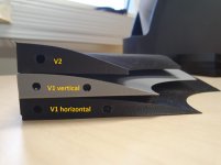
Waveguide version 2 fresh from the oven. The effective depth is the same as in V1, but the lateral size is considerably smaller. Unlike V1, V2 symmetric between vertical and horizontal directions. There's also files for V3, which is the same size as V2, but with some extra depth, but I'll probably measure the V2 before printing it.
Attachments
- Home
- Loudspeakers
- Multi-Way
- 3-way active standmounts with coax upper end & Other UniQ adventures