Good looking driver.
Still, I don't think your are going to get much controlled directivity with the driver (above about 2.5 kHz it will be modestly directive).
The KEF R3 data shows what can be achieved with a 5.25" Uni-Q in terms of directivity.
KEF R3 Speaker Review
To get a low diffraction signature either have a large baffle (moving diffraction much lower in freq. to keep it out of the >800 Hz range) OR consider a large sphere (for a more uniform profile).
Maybe I'm too conservative, but I was thinking something like a heavily rounded baffle machined from three layers of 19mm MDF.
Attachments

Hi,
For a roundover to be effective at 1khz it needs 10cm radius.
So either you'll have to widen your box either you'll have to play with xover freq to 'shade' diffraction if you want to keep your box initial width.
For a roundover to be effective at 1khz it needs 10cm radius.
So either you'll have to widen your box either you'll have to play with xover freq to 'shade' diffraction if you want to keep your box initial width.
Could add slots beside the coax and make a passive resistive enclosure for cardioid like response down much further.
Hi,
For a roundover to be effective at 1khz it needs 10cm radius.
So either you'll have to widen your box either you'll have to play with xover freq to 'shade' diffraction if you want to keep your box initial width.
I think we should consider the baffle rounding as part of the waveguiding structure. What matters is the acoustic impedance of the geometry formed by the cone + possible additional waveguide surrounding it + the flat part of the baffle + the rounding.
^ Hi,
Yes i agree roundover can be seen as part of a waveguide: member Patrick Bateman investigated and reported his thoughts in multiple thread in the last years and tbh most of his discoveries convinced me as i was in part sceptical at first ( some of his conclusions are controversial though).
Worth looking for them imho. Same for E.Geddes works ( Suma loudspeakers and white papers availlable @Gedlee site).
But it is easy to check the roundover effect through simulation software (eg: Vituix cad).
Could add slots beside the coax and make a passive resistive enclosure for cardioid like response down much further.
I have been considering adding removable panels to the sides. This would allow using the enclosure either as a regular sealed box or passive resistive enclosure depending on what kind side panel inserts are used. So kind of keeping this option but not having to design it yet 😀 On the other hand, not doing this would allow enclosing the coaxial driver using a cone that attaches to the backside of the baffle.
^ Hi,
Yes i agree roundover can be seen as part of a waveguide: member Patrick Bateman investigated and reported his thoughts in multiple thread in the last years and tbh most of his discoveries convinced me as i was in part sceptical at first ( some of his conclusions are controversial though).
Worth looking for them imho. Same for E.Geddes works ( Suma loudspeakers and white papers availlable @Gedlee site).
But it is easy to check the roundover effect through simulation software (eg: Vituix cad).
Thank you krivium. Those are good sources. I've already studied them to some extent, but not enough. The acoustic horn design thread is another very good source. A well optimized waveguide+baffle+roundover is pretty much the same thing as a free-standing horn with optimized termination.
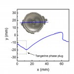
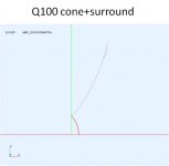
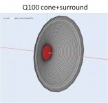
There was also some progress today since I was able to 3d scan the cone profile of the Q100 driver. It turned out be a difficult subject due to the combination of reflective metal surfaces combined with a black rubber surround, but eventually I was able to get quite reliable data for area of interest. The scan was made with Artec Eva. Now I can start designing the interface between the cone and the baffle.
Attachments
The KEF R3 data shows what can be achieved with a 5.25" Uni-Q in terms of directivity.
-which isn't *good (not uniform off-axis) with it's own crossover from 2-3.5 kHz:
https://www.audiosciencereview.com/...een-shot-2020-03-14-at-10-51-11-am-png.54234/
Definitely move the tweeter's high-pass as low as possible.
Even then though.. maybe 1.6-1.7 kHz??? for the off-axis transition between cone and cone-loading for the tweeter? My guess is though that the cone won't load that low - so there will likely still be that "bloom" in pressure off-axis somewhere between 1.8-3 kHz.
*it's also not "good" in the context of wanting more directional behavior: a Unity horn could have provided a LOT more and "even" directive polar profile. Still, I tend to prefer LESS directive designs (at higher freq.s), so even though you were originally describing something more directive - you might well be creating something you find subjectively preferable.
Last edited:
-which isn't *good (not uniform off-axis) with it's own crossover from 2-3.5 kHz:
https://www.audiosciencereview.com/...een-shot-2020-03-14-at-10-51-11-am-png.54234/
Definitely move the tweeter's high-pass as low as possible.
Even then though.. maybe 1.6-1.7 kHz??? for the off-axis transition between cone and cone-loading for the tweeter? My guess is though that the cone won't load that low - so there will likely still be that "bloom" in pressure off-axis somewhere between 1.8-3 kHz.
*it's also not "good" in the context of wanting more directional behavior: a Unity horn could have provided a LOT more and "even" directive polar profile. Still, I tend to prefer LESS directive designs (at higher freq.s), so even though you were originally describing something more directive - you might well be creating something you find subjectively preferable.
I think that R3 measures pretty well in general, but that 2-3.5 kHz range could be better. I'd like to think that something can be done to improve it with acoustic design and dsp. More about that later.
Perhaps I should have written smooth directivity rather than controlled directivity. I'm not sure if I was using the term correctly. Anyway, I'm not aiming to very narrow response. Just trying to achieve something that I think will work in our living room (rather small with mostly rigid walls) and provide good imaging and wide listening spot. Preference is a good point. I have not experience of very directive speakers in this kind of rooms, so I can't really say would I like it or not. Hence, I'm not going there.
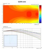
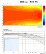
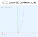
I ran some simulations for the twitter response in the Q100 cone in IB. An additional waveguide (flare) was added to mate the cone to the baffle using the oblate spheroid - super ellipse formula. So I played with the equation parameters in order to fit the inner part of to the cone shape and to obtain a suitable overall radius for cone+WG. Note that the cone limits the achievable waveguide shapes in such way that the conical-like region cannot be made very long. R120 is for a diameter matching the size of the woofer (L26RO4Y). R170 is 10cm larger in diameter, and would require ~40cm wide baffle. Both extend to directivity towards lower frequencies and give some more freedom for choosing the XO frequency.
Attachments

Last edited:
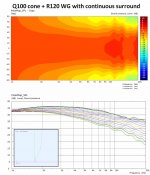
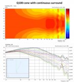
I did also some more simulations in order to understand the effect of the surround. In q100 it is formed by a rather flat structure except for 36 equally spaced bumps. In between the bumps, the surround continues the shape of the cone. I took the size and position of the bumps from the 3d scan (post 48) and modeled them as a circularly symmetric ring. The height and width of the ring were the actual measures of the bumps. The resulting simulation geometry is a circularly symmetric surround which has the dimensions of the highest point of the bump. So in comparison with the real shape, it should over estimate the disturbance at the cone edge. The results are shown with and without the additional waveguide. Interestingly, the flare seems to reduce the effect of the surround. I suppose for a regular driver flush-mounted to a flat baffle, the disturbance caused by the surround is located at a place where there is already a discontinuity of the waveguide shape due to the abrupt cone-baffle interface.
Attachments
Last edited:
^Looking at this again with fresh eyes and mind: I don't buy the result. I should at least test it with a finer grid.
Ok. I confirmed that the effect is of the surround is similar for the bare cone in IB and for the cone+WG in IB. So ^^ is not correct. The error was that I ran the convergence test only for the larger structure (cone+WG) and assumed that the smaller structure would converge with the same number of mesh points. For some reason that was not the case.
Currently I'm running 3D simulations for towards the real WG-baffle design. This obviously are much more time consuming than working with the circular symmetry, so it may take some time before I have anything to show.
Currently I'm running 3D simulations for towards the real WG-baffle design. This obviously are much more time consuming than working with the circular symmetry, so it may take some time before I have anything to show.
I'd suggest getting real measurements on a baffle with some *3d printed parts to see what the transition is doing (from surround to guide).
I'd suggest getting real measurements on a baffle with some *3d printed parts to see what the transition is doing (from surround to guide).
That's exactly what I'm planning to do. Ath is a very nice tool for sketching the 3D waveguide so that's pretty much what I'm doing at the moment, mostly just to have some preliminary waveguide shape and an estimation for the baffle size. I would trust measurements much more than my 3D simulations of freestanding structures😀
Cheers to everyone who have shared links to suitable coaxial drivers. Looks like this project will proceed with the Kef Q100 drivers, but I tried to collect all links to the first post as a future reference. Perhaps someone will find it useful.
A quick update on the driver choice: I just acquired a nice second hand pair q100 speakers in white. Should match nicely with L26ROY at least visually.
Oh, you've got a pair of exactly the right drivers, I'd say you already almost win.
By the way, mid to high frequency directivity error shown in the EAC's test is mainly caused by inappropriate mounting (as you might notice, it was not flush mounted), so do not worry.
Last edited:
- Home
- Loudspeakers
- Multi-Way
- 3-way active standmounts with coax upper end & Other UniQ adventures