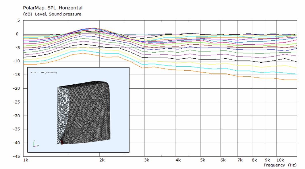
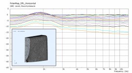
It's been quite intensive at work lately, but I have tried to keep also this project alive. I continued the ABEC/Ath simulations by morphing the circular symmetric waveguide into a 3D form with a rectangular mouth. In an infinite baffle it simulates similarly to the circular symmetric profiles shown before. Then I added some edge rounding and removed the infinite baffle, and got a taste of all sorts of numerical issues and long simulations times required for sorting them out. Here's the most reliable data I have obtained for the tweeter response so far (these took around 8h to solve).
Horizontal polars for the tweeter
Vertical polars for the tweeter
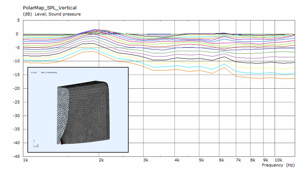
I'm still not sure how accurate the baffle edge effects at around 2 kHz are. They seem to depend a lot on the computation mesh and placement of the subdomain interface even if the baffle/WG shape remains unchanged.
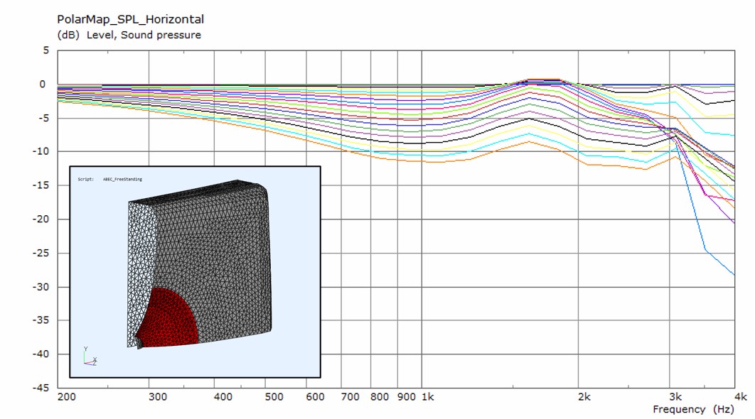
Here's similar simulations for the coaxial mid cone.
Horizontal polars for the mid
Vertical polars for the mid
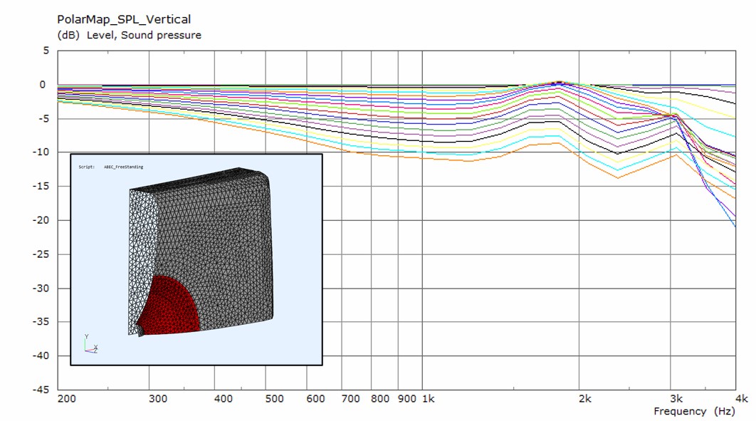
The design goal would be to obtain smooth directivity and try to manage the edge diffraction effects. The challenge in comparison to real horns and waveguides is that the shape of the mid cone sets quite strict limitations to what kind of waveguide profiles can be achieved using the oblate spheroid + super ellipse formula. There's might also be a tradeoff that extending the directivity to lower frequencies requires a large waveguide. Consequently, the baffle has to be large and thus larger rounding is required to manage the baffle edge effects. I also find it difficult to get reliable simulation data for the baffle rounding effects because having dense enough computation mesh at the edges of the baffle mean insanely long simulation times. Hence, I think it's time to move to experimentation.
Horizontal polars for the tweeter
Vertical polars for the tweeter
I'm still not sure how accurate the baffle edge effects at around 2 kHz are. They seem to depend a lot on the computation mesh and placement of the subdomain interface even if the baffle/WG shape remains unchanged.
Here's similar simulations for the coaxial mid cone.
Horizontal polars for the mid
Vertical polars for the mid
The design goal would be to obtain smooth directivity and try to manage the edge diffraction effects. The challenge in comparison to real horns and waveguides is that the shape of the mid cone sets quite strict limitations to what kind of waveguide profiles can be achieved using the oblate spheroid + super ellipse formula. There's might also be a tradeoff that extending the directivity to lower frequencies requires a large waveguide. Consequently, the baffle has to be large and thus larger rounding is required to manage the baffle edge effects. I also find it difficult to get reliable simulation data for the baffle rounding effects because having dense enough computation mesh at the edges of the baffle mean insanely long simulation times. Hence, I think it's time to move to experimentation.
Attachments


Here is half of the rectangular WG from Ath 3D printed in PLA. The other half is being printed right now.
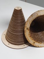
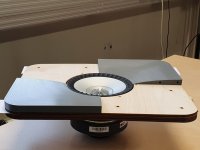
The 3D printed part stands on top of three layers of laser cut 4mm plywood which includes holes for alignment pins and mounting holes for the UniQ driver. The size of the WG is 300 mm x 250 mm, and the plan is to mount it on a 360 mm x 560 mm test baffle. I have some R=21mm quarter round pine trims that I'm planning to use for baffle rounding for the first tests and the figure out a way to increase the radius.
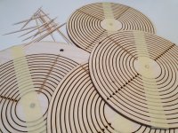
I also crafted conical enclosures for to be mounted to the backside of the baffle. These are 57 layers of laser cut 4mm plywood glued together using toothpicks for alignment. Insane, huh? 😀 Well, it's nice and rigid considering the 5mm wall thickness and not much material was wasted. Some supports to be added later and the rear end will be supported to the back baffle of the enclosure.
The 3D printed part stands on top of three layers of laser cut 4mm plywood which includes holes for alignment pins and mounting holes for the UniQ driver. The size of the WG is 300 mm x 250 mm, and the plan is to mount it on a 360 mm x 560 mm test baffle. I have some R=21mm quarter round pine trims that I'm planning to use for baffle rounding for the first tests and the figure out a way to increase the radius.
I also crafted conical enclosures for to be mounted to the backside of the baffle. These are 57 layers of laser cut 4mm plywood glued together using toothpicks for alignment. Insane, huh? 😀 Well, it's nice and rigid considering the 5mm wall thickness and not much material was wasted. Some supports to be added later and the rear end will be supported to the back baffle of the enclosure.
Attachments
Last edited:
Hello Mr Sticha
I am also utilizing a Kef coax for my project. I'm using 2x7" woofers though.


Q100 midwoofer has a resonance at 1100-1200Hz that is quite visible in gated measurements and should be dealth with. No problem for you since you'll be using dsp but wanted to mention it since i don't know how will your measurements be done and how resolute will they be.
I am also utilizing a Kef coax for my project. I'm using 2x7" woofers though.
Q100 midwoofer has a resonance at 1100-1200Hz that is quite visible in gated measurements and should be dealth with. No problem for you since you'll be using dsp but wanted to mention it since i don't know how will your measurements be done and how resolute will they be.
Last edited:
Thank you for the heads-up Zvu. That's definitely a useful bit of information.
Nice project you have there! That's a newer r series Uni-Q, right? Is the resonance problem fixed by the ribbed cone?
Nice project you have there! That's a newer r series Uni-Q, right? Is the resonance problem fixed by the ribbed cone?
Hi, nice! Modern manufacturing techiques at work 🙂
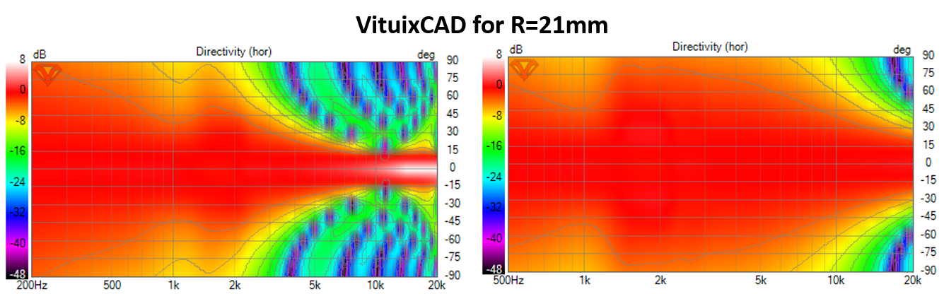
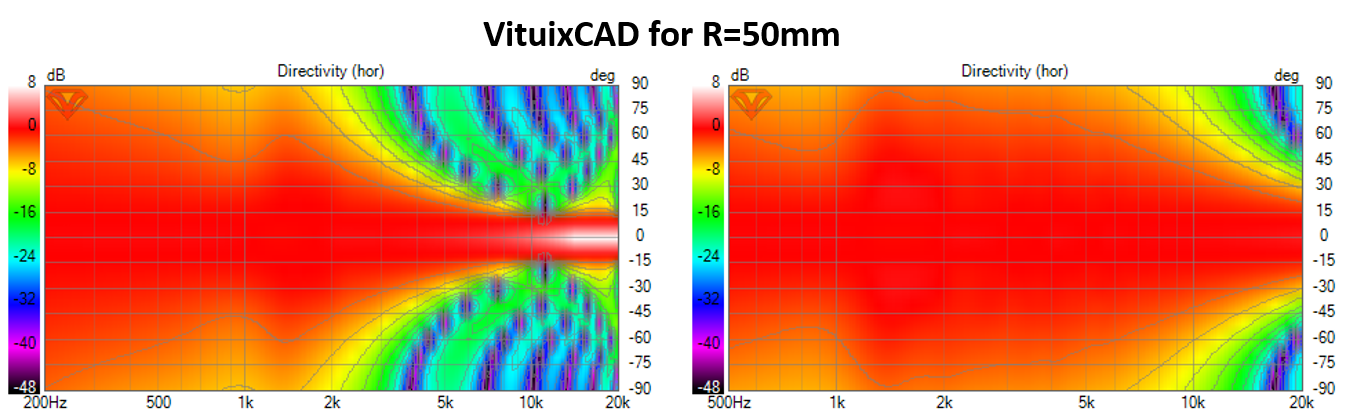
For the roundovers, you can use vituixcad diffraction simulator and find out pretty fast how big r roundovers are effective for your application, for the ~1.5kHz issue.
For a flat baffle best results in vituixcad diffraction tool is achieved when the roundover starts right at the driver rim so that flat baffle area in minimized. This means large roundovers if the box has to be wide, and no roundovers when the box is as narrow as possible. Wide with roundovers is a bit smoother but a lot harder to manufacture. You could 3D print the roundovers though.
I have access to 3-axis CNC so eventually I will embed the 3D printed WG in an CNC machined mdf (e.g. three layers of 19mm stacked). What I wrote above was just related to the test baffle for first measurements, which will involve use of cardboard tube or something like that for testing larger roundovers. My plan is to start the rounding right at the edge of the WG and use smooth splines that match the curvature of the rounding to both the WG and the sidewall of the enclosure. This means that larger rounding curvature requires either a wider enclosure or smaller WG. The optimist in me thought that a radius of around 3cm would be enough if it's nicely matched to the waveguide, but that thought was not really based on physics. I suppose I thought that the WG would do some magic there, but now I'm starting to realize that it mainly limits a bit the energy that reaches the edge. Quick testing with VituixCAD shows >50mm is what is needed.
The simulation is probably a bit worse than the reality, because I was using 90deg symmetry. The driver will have different distances to top and bottom edges of the real baffle. Perhaps that and increase of rounding for the sides could do the trick, but I'll still start with the small rounding in order to see how the measurement compares to the simulations.
The simulation is probably a bit worse than the reality, because I was using 90deg symmetry. The driver will have different distances to top and bottom edges of the real baffle. Perhaps that and increase of rounding for the sides could do the trick, but I'll still start with the small rounding in order to see how the measurement compares to the simulations.
Thank you for the heads-up Zvu. That's definitely a useful bit of information.
Nice project you have there! That's a newer r series Uni-Q, right? Is the resonance problem fixed by the ribbed cone?
I'll try to find my 10ms gated raw measurement of q100 midwoofer.
Yup, that's new R series coax from 2018.
I don't think that resonance origins at cone but that it is a product of Z-flex surround. In LS50 suspension it is treated with some tacky coat of damping material to minimize the effect.
In R series there was a resonance arround 1kHz but i'm not sure if it is because of driver mounting that was done very poorly in pre 2018 R series. I see no hint of resonance in new R series.
All that being said, the proof will be in the measurements
Last edited:
Very nice works from both of you!
Zvu, will they be sealed or ported?
MrSticha, pvc pipe could be used for roundover experiment. I'm jealous of the tools you have access to!
Zvu, will they be sealed or ported?
MrSticha, pvc pipe could be used for roundover experiment. I'm jealous of the tools you have access to!
I intend to make it ported but will predict port plugs when/if used with subs. I find my inspiration in HEDD mk2 monitors. Woofers will probably be active with high level input and D-class amps. Passive for mid-high, so 4 amp channels total.
That would be great. I'm doing the measurements in our apartment so 10ms window is out of reach.I'll try to find my 10ms gated raw measurement of q100 midwoofer.
Btw, what kind of enclosure volume do you have for the UniQ and what's the XO frequency for mid/bass?
Last edited:
MrSticha, pvc pipe could be used for roundover experiment. I'm jealous of the tools you have access to!
Thanks for the tip. I'm lucky to have these opportunities at the moment, but on the other hand I'm really missing the good old garage workshop of my own.
That would be great. I'm doing the measurements in our apartment so 10ms window is out of reach.
Here it is on axis and 45 degrees off axis. Gate is somewhere between 10-12ms


Given how much trouble we diy-ers go through untill we get the drivers (that are not availabe for single purchase or as a spare part), we try hard about the finish and woodwork - i think it is worth it to do what ever it takes to make it better product than what it was intended to be.
Btw, what kind of enclosure volume do you have for the UniQ and what's the XO frequency for mid/bass?
It is closed rectangular cabinet for midrange with 3,2 liter neto volume. Less when damping material is added. I usually make midrange chamber as big as i need to push the first mode bellow midrange low cutoff, but.. this being KEf coax i examined their cabinets and see that they don't use much volume behind the midrange.

Maybe they know something i don't about their midrange so i decided to test it in such a small enclosure to see how it sounds and measures.
Target for bass/mid crossover frequency is around 300Hz but i intend to utilize my nanodigi to have a listen before i decide. My friend and i made a test with his dsp trying to add 6" bass bellow his Q100 coax (in modified cabinet with modified passive crossover). Point of the experiment was to see how Q100 behaves without having to play low frequencies. We moved the crossover frequency between bass cabinet and Q100 cabinet from 150Hz to 300Hz in 50Hz increments. 150 sounded muffled and every next step sounded better. I couldn't hear any advance going from 250Hz to 300Hz - it sounded the same to me. With every 50Hz above starting point which was 150Hz, midrange sounded cleaner and cleaner. In short, that's how i predict about 300Hz to be fine for my midrange, but i'll certainly do the same test to see what i come up with.
Last edited:
Mister Sticha!
Are you really gonna run it with TPA3255 4x150W + 2x300W? You have to trim them down quiet a bit to have some bitdepth in that DSP or are you gonna run it analog trough?
Atm i run a 4 way system with a sum equalent to 2x140w/8ohm. Direct coupled 4 ohm drivers can sound loud at small watts when summon together. But my listening room is only 30m2 though.
Last edited:
Thank you for measurement data and wise words Zvu. My cones are 2 litres in their current form, but there will be an additional 0.5-1 litres resulting from how they are interfaced with the front baffle, so seems like we are landing in the same territory in terms of both mid enclosure volume and intended XO frequency. It's comforting to know that someone with way more experience with KEF coaxials is having similar thoughts, in particular when they are based on real experiments.
Mister Sticha!
Are you really gonna run it with TPA3255 4x150W + 2x300W? You have to trim them down quiet a bit to have some bitdepth in that DSP or are you gonna run it analog trough?
Atm i run a 4 way system with a sum equalent to 2x140w/8ohm. Direct coupled 4 ohm drivers can sound loud at small watts when summon together. But my listening room is only 30m2 though.
Taking a closer look at the gain structure is on my to-do-list, but I haven't had time to do it yet. I have tpa3255-2ch-260w and tpa3255-1ch-480w, two boards each. MiniDSP 4x10 allows reducing the gain of the balanced output stage by a factor of two and dropping down the gain at input stage of TPA3255 by changing opamps might be an option as well. Let's see. I'll add post-DSP attenuation if needed. L26RO4Y and the KEF mid have fairly low sensitivity, but adding an L-pad for the tweeter might be a good option. But as I said, I have to take a closer look later.
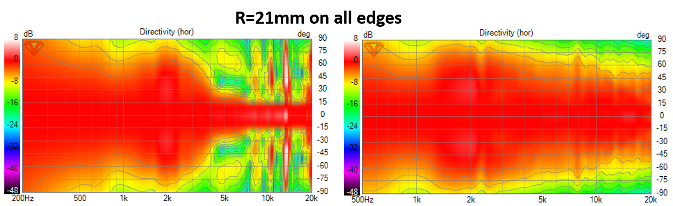
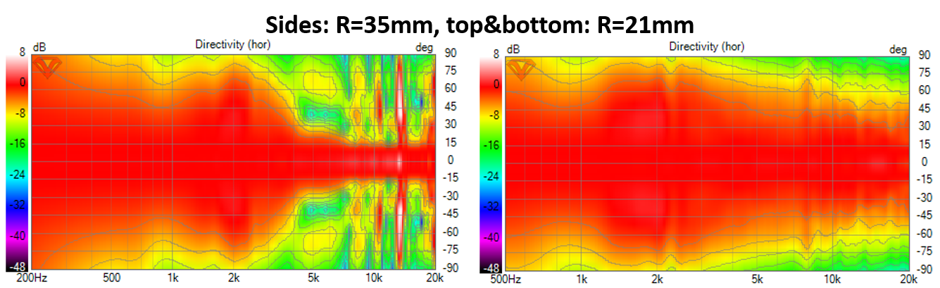
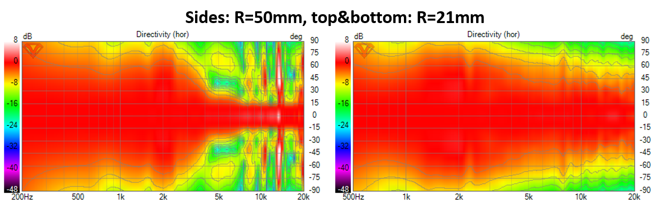
Here's some measurement data for the first baffle+waveguide iteration. First some notes
So in short, none of the tested edge roundings really helped with the baffle edge diffraction. I expected this based on the VituixCAD diffraction calculations.
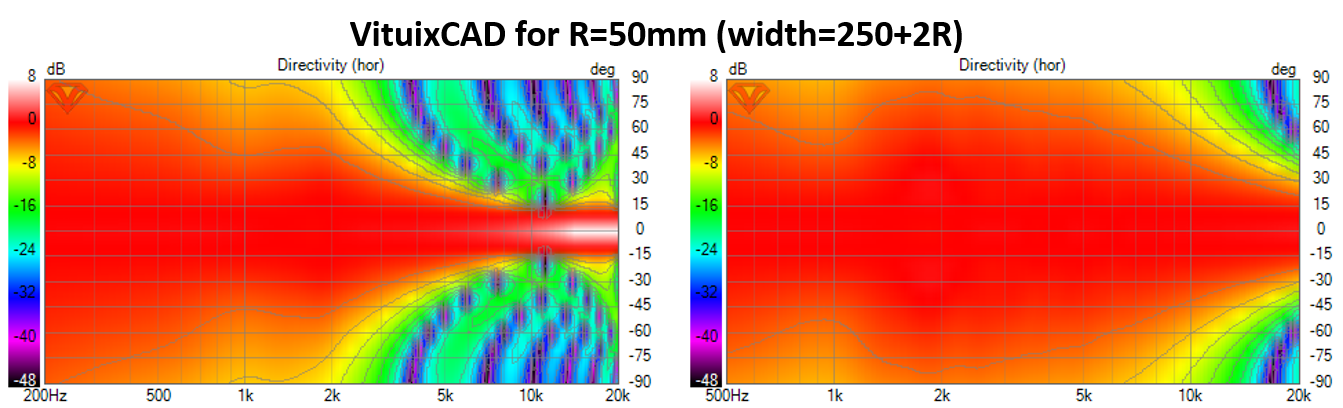
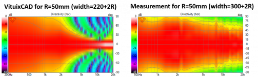
I did not go beyond R=50mm because I don't think it's practical. Every time I increase the radius, I also increase the baffle width so the problem shifts to longer wavelength where a larger R would be needed to fix it. Next step is the draw and print a new narrower waveguide which allows using narrower baffle. Here's what VituixCAD gives for R=50mm on a 50mm narrower baffle. These are the dimensions where the the rounding starts to mitigate the diffraction problem.
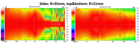
- The fixed part of the baffle was 300 mm wide and 500 mm tall in all measurements.
- The waveguide is 300 mm wide and 250 mm tall.
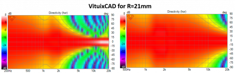
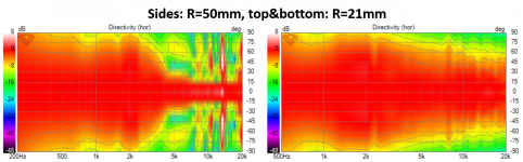
- The rounding radius R was 21mm for top and bottom edges in all measurements
- The R on the sides was varied (R=21, 35, 50mm) by adding different quarter round objects on the sides of the baffle. The attached picture shows the case of R=21 mm.
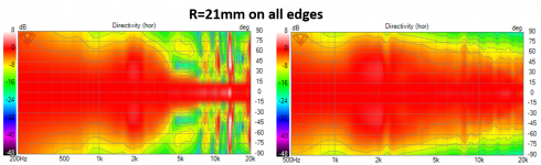
- Driver mounting could be improved since it was protruding by ~0.5mm or so (picture)
- Data was recorded using REW, UMC204HD, and Sonarworks SoundID. I was forced to limit the gate to 4 ms this time.
- 7.8 uF was added in series with the tweeter
- All data normalized to 10 degrees.
So in short, none of the tested edge roundings really helped with the baffle edge diffraction. I expected this based on the VituixCAD diffraction calculations.
I did not go beyond R=50mm because I don't think it's practical. Every time I increase the radius, I also increase the baffle width so the problem shifts to longer wavelength where a larger R would be needed to fix it. Next step is the draw and print a new narrower waveguide which allows using narrower baffle. Here's what VituixCAD gives for R=50mm on a 50mm narrower baffle. These are the dimensions where the the rounding starts to mitigate the diffraction problem.
Attachments


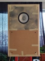
This is probably close to optimal in terms of how the woofer response comes from VituixCAD. The baffle diffraction provides just a bit of narrowing to allow constant directivity from 1 kHz to 2 kHz from where the tweeter takes over. The measured tweeter response already matches that quite well from 5k to 20k. Next I should to experiment with the 220 mm wide waveguide to see how it works with R=50mm side edge rounding in the 2-5 kHz range.
It also seems that I'm approaching Genelec 8260 (from the 1st post) in terms of baffle width and waveguide shape😀
It also seems that I'm approaching Genelec 8260 (from the 1st post) in terms of baffle width and waveguide shape😀
Attachments
Last edited:
Why bother with a coax
If max Spl is not a problem I will consider in op's shoes to try a very good 3" FR in a WG... or not.
That means for instance one which has good and clear subjective highs and good tones like the Scan Speak 10F , 4 ohms being sligthy flater than the 8 ohms.
Of course it ask a higher cut-off (some tried 300 hz but the max spl is a problem) and baffle step may be a challenge. 500 hz LR2 is a feasible if not the best target or 800 hz with more LR3 or higher order XO which will be less nice than a cool LR2. So the choice of the Seas LROY may be a problem below cause the bafle step in relation to its low spl and size mismatch for the polar response in the cut off overlapp.
But the 500 hz to 20k hz of the Scan Speak within 30° will sound better than most coax with a passive XO in the 2k to 4 Khz.. Ah why not something like a Linkwitz LR mini design but with a bigger driver that fire up than the one chosen by Linkwitz ?? For instance a nice 10" from Faital ?
Some also seems to like Mark Audio bigger FR for that task and some MOA serie became cheaper.
Imho, YMMV, my 2 cents
PS : there is as said the unity way but the DIY work is always challenging as the difraction at the horn mouth VS a smoother cabinet à la Genelec... though it doesnt stop to make sleep some good monitors like the D&D 8C which is quite cubic despite having a WG. A Heissmann design close look may be nice.
so my 4 cents.
Last edited:
..what's it like with baffle and no waveguide?
Note there are two other approaches to consider with respect to "box" design:
1. Spherical - as with wood/bamboo salad bowls.
2. Absorption along the areas of diffraction.
Note there are two other approaches to consider with respect to "box" design:
1. Spherical - as with wood/bamboo salad bowls.
2. Absorption along the areas of diffraction.
Last edited:
2- perhaps a square of felt around the cabinet indeed. Bu too bad not to see WG for these cool 3" drivers to blend with 8" to 12" driver below 🙂
Or maybe this Genelec 8020 DPM – Thomann France above a 12" that is firering up à la Linkwitz LR in order to avoid a BS and get a smoother blending ? Notice the cool price...
Or maybe this Genelec 8020 DPM – Thomann France above a 12" that is firering up à la Linkwitz LR in order to avoid a BS and get a smoother blending ? Notice the cool price...
- Home
- Loudspeakers
- Multi-Way
- 3-way active standmounts with coax upper end & Other UniQ adventures