Well I read it and it has some demands and still has a bulk capacitor in the (conceptual) schematic....
Where?
I see resonant capacitors and a small filter capacitor on the output.
In practice there will be EMI filtration on the mains.
Best wishes
David
There is no value mentioned in the 2011 conceptual schematic. The text says: "This clearly results in much reduced size of filtering capacitors needed, hence in reduced size and cost of the three-phase rectifier." which says eh...not much. In the case of audio the added cost of a 3 phase transformer and/or the complex electronic control of semis will probably outweigh the bonus of smaller capacitors.
Last edited:
Maybe 400 V DC...is not that OK for a power amplifier.
400V is just the bus, there is the option for an isolation and step down transformer.
There is no value in the schematic.
Which schematic, which capacitor?
IF you can't include a reference then you could just snip the picture and circle what you think is the "bulk" capacitor.
Best wishes
David
It can be made as simple or as complex as one wishes but I see the challenge. Step-down transformers will be a novelty in DC. Good luck with the design, please make sure to use all safety measures as common in 3 phase/high power applications.
Last edited:
Whether your three phase AC supply is feeding a conventional transformer / rectifier circuit, or a rectifier / SMPS circuit, the elephant in the room is the rectifier; after that you no longer have the constant power advantage of 3-phase AC. Audiofan pointed this out correctly in back in post 30.
So you still need large capacitors to smooth the rectified voltage waveforms (though not as large as single phase). However the ripple frequencies and harmonics will be more objectionable and potentially harder to keep out of audio circuits.
So you still need large capacitors to smooth the rectified voltage waveforms (though not as large as single phase). However the ripple frequencies and harmonics will be more objectionable and potentially harder to keep out of audio circuits.
In the case of audio the added cost of a 3 phase transformer and/or the complex electronic control of semis will probably outweigh the bonus of smaller capacitors.
I am not sure I can agree with the above because of the following reasons:
1) The 1ph tfr has two legs and the 3ph tfr needs only three, as the centre leg maybe removed (iron comparison).
2) 1ph is 2-wire but even 3ph is only a 3-wire circuit (wiring mess comparison).
3) For a given power, a 3ph system (rectifier/inverter/motor/whatever) will always have lesser per-phase current when compared to single phase (copper thickness comparison).
4) The 3ph rectifier output has a minimum standing DC voltage that is equal to 0.866Vm even at heavy load (and no capacitor), whereas the standing DC of the 1ph rectifier is only due to the capacitor, which becomes prohibitively large for heavy loads due to increased voltage droop (voltage droop comparison).
5) Even for PFCs, the output capacitor for 1ph is larger due to the double frequency ripple voltage carried by it. For a 3ph PFC, this output ripples for all phases are cancel each other, as a^2+b^2+c^2=const., i.e. constant power gives clean DC (PFC power quality comparison)
6) Power factor of 1ph rectifier is inherently poor, as the conduction angle is narrow and a large capacitor and its poor reliability are inevitable. Though smaller capacitors can improve pf, the voltage droop and holding time (for critical loads) are also compromised. In the 3ph case, a high pf is easily achieved, and a large capacitor is not needed, even for small droop (pf comparison).
7) Single-phase circuits don't eliminate any harmonics, but an ungrounded 3-ph star circuit easily eliminates all triplen harmonics, improving THD and pf. Note that the 3rd harmonic, which is the most dominant in a power system, being triplen, also gets eliminated (harmonics comparison).
So, I think, if there's enough power to be delivered, then three-phase is unbeatable in terms of performance (at least for a given power).
johnmath said:However the ripple frequencies and harmonics will be more objectionable and potentially harder to keep out of audio circuits.
That's precisely why an active PFC is frequently used for 3-phase applications. The output voltage and input current of the 3-phase rectifier have ripple and harmonics respectively, but both these quantities for the 3-phase PFC are rather pure, i.e. DC and sinewave, as desired. That also explains why active PFC is more important for 3-phase rectification than it is for single phase, in which case the output exhibits a 2f ripple, in spite of all the control.
Last edited:
I need about +-100 V...
I expected something like ±100V, but how many amperes are you planning to draw at that voltage? That should directly tell you if you need any PFC, irrespective of converter topology.
First is a 3 phase rectifier to power the usual SMPS DC drive circuitry for a hi-frequency transformer for step down and isolation....Second, the Cuk rectifierless....
Sir, once again your rectified output for 400V (line) would be 560VDC (min). Now, the current draw at this voltage would be really small even for a 1kW SMPS, which is a good thing as finding devices would be easier. However, since you're approaching the limits of LT voltages, it would be better to comply with IEC60950-1 (attached) while designing the SMPS, in case you decide to take this route.
Here the transformers are running at 50Hz and conventional, so the above clearly doesn't apply. I hope you already guessed that you could also use the 12-pulse arrangement with regular diodes instead of thyristors, since you already have the transformer for stepping things down.Third, just simple transformer, rectifier and capacitor....Fourth is delta + Y transformer...
I'm sorry, I didn't see this post yesterday, and even replied to ones that came later.
Attachments
Last edited:
Page 13 of the following document shows the portions of the IEC 60950-1 standard that are applicable to SMPS design.
Design_Considerations
However, please note that the minimum creepage distances were updated by the 2013 version of the standard (Table 2N, Pg 107-108, attached). The IEC60664-1 standard which is also often used by SMPS designers, recommends the same creepage distances in 60950-1 (hence not attached).
Attachments
So, I think, if there's enough power to be delivered, then three-phase is unbeatable in terms of performance (at least for a given power).
Exactly, that is what I wrote but you overlooked the "audio". That is why 3 phase power is used for higher power/industrial applications and in general not in private homes let alone audio. For high power industrial applications there is also little other choice 🙂
Choosing high power solutions for relative low power applications is nearly always an expensive choice. One discovers when searching a suitable 3 phase transformer for audio. DIYing a safe working 3 phase SMPS with high efficiency ideas from the solar/car industry for let's say 2 kW load in total is an exercise in itself probably not leaving the design phase. Much effort for the already ear destroying 1W level 😀 OK, that is per channel.
Last edited:
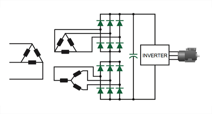
3 phase SMPS are very complex from my experience I wouldn't recommend one as DIY project unless your very keen. However if you are the best design is the Vienna Rectifier:
Vienna rectifier - Wikipedia
Note the insane power density and very 'ideal load' characteristics. There are significant practical implementation details that are not covered in academic literature. For example consider that real AC has harmonics and so to draw an in phase current and pass EMC you must consider up to around the 50th harmonic. This results in needing a very powerful DSP or FPGA controller.
In terms of connectors, look at what Powersoft used in the x8:
X8 - Powersoft
I expected something like ±100V, but how many amperes...?
It's hard to specify, this is the central power supply for a home theatre system.
So 3 amplifiers for the L, C R main speakers plus 4 amplifiers for L & R surrounds plus L & R rears, plus 2 subwoofers.
Maybe 25 amps if they are all required at once for a special effect.
...your rectified output for 400V (line) would be 560VDC (min)
I plan to have Y connection rather than delta so 240 V line and 340 V DC.
I'm sorry, I didn't see this post yesterday, and even replied to ones that came later.
No problem, on the contrary, you showed more patience and civility in your replies than their objections deserved IMHO.
You made this comment earlier about the Cuk paper, you appear not to have understood it....efficiency ideas from the solar/car industry
You said "where the focus is on efficiency at relatively constant high power."
when in fact the paper presents data for exceptional efficiency at low loads and emphasises the improved ability to respond to load variations .
1W level 😀 OK, that is per channel.
If you think 1 W is adequate then yes, 3 phase is quite pointless.
However, that sort of power is so inadequate for a quality system that I assume it's a troll.
3 phase SMPS are very complex from my experience I wouldn't recommend one as DIY project unless your[e] very keen... ...Vienna Rectifier:
I don't plan a very complex 3 phase SMPS, that would be overkill.
A simple 3 phase rectifier followed by a one phase SM transformer would be fine, if I can find one commercially.
The Cuk stuff looks brilliant but would probably be a multi-year development project in itself.
I discovered the Vienna rectifier just before NV2008 mentioned it.
That looks like another multi-year project, no thanks😉
In terms of connectors, look at what Powersoft used in the x8:
X8 - Powersoft
Thanks, brilliant -a heavy duty audio system powered by a 3 phase supply with a removable connector, just what I had in mind.
The connector looks perfect, do you know what it is or if it's readily available?
Or a schematic of the power supply?😉
Best wishes
David
Last edited:
Did you ever measure how many Watts it is when the volume is already deafening? Take some headroom into account for dynamics and some relatively efficient speakers and 10 ...50W amplifiers are more than adequate in the majority of cases. I think many projects here are in the same ballpark like the ACA with its 6W and the F5 with 25W.
Please call yourself names. I understood the paper quite good, thank you. This was the complete sentence for the right context:
Contrary to your project the 2 x 4W amplifier (designed as a challenge how much power one really needs) is designed, built and playing. It never plays louder than 1W (even less but I round it) which is already above the comfort zone of many.
Please call yourself names. I understood the paper quite good, thank you. This was the complete sentence for the right context:
DIYing a safe working 3 phase SMPS with high efficiency ideas from the solar/car industry for let's say 2 kW load in total is an exercise in itself probably not leaving the design phase.
Contrary to your project the 2 x 4W amplifier (designed as a challenge how much power one really needs) is designed, built and playing. It never plays louder than 1W (even less but I round it) which is already above the comfort zone of many.
Last edited:
Are you sure you want up to 25 amplifiers to use a single common +/- power supply, which will mean a single 0V ground reference. Are all the input signals for all the amps coming from isolated sources, so as to avoid issues with hum loops ?
It never plays louder than 1W (even less but I round it) which is above the comfort zone of many.
What is the sensitivity of your speakers, especially in the bass?
At what distance do you listen?
Best wishes
David
Are you sure you want up to 25 amplifiers to use a ...common +/- power supply
Not sure but it looks like the best option.
Isn't this essentially what any AVR does?
Seems like even more potential for loops if I have multiple power supplies.
With one central supply I can have a well defined star point.
...from isolated sources, so as to avoid issues with hum loops ?
The sources are all differential, XLR output DACs are now almost default for better quality units.
Best wishes
David
Exactly, that is what I wrote but you overlooked the "audio".
Actually, I did notice the "audio" part, but did not assume "audio" and "low power" to be synonymous, as I did not distinguish between audio and non-audio loads. I was waiting for the OP to return with some information on amplifier input power.
jean paul said:Choosing high power solutions for relative low power applications is nearly always an expensive choice. One discovers when searching a suitable 3 phase transformer for audio.
Well, if the OP is alright trying it, then I'm there to help. Besides, the OP has claimed some prior experience with 3-phase power, and so I made a reasonable assumption that he knew (at least to a fairly good extent) about what he wanted.
Low power 3-phase transformers are standard laboratory equipment that are frequently procured by colleges/polytechnics. Since, these are meant for demonstration/instruction/teaching purposes, they're often rated less than 1-2kW. Then there's also the possibility of a bespoke transformer.
jean paul said:DIYing a safe working 3 phase SMPS.... is an exercise in itself... Much effort for the already ear destroying 1W ...
Very true, but the OP appears to be a brave person, who also happens to slowly move through the various steps, really carefully, after studying things well. I, therefore, tried my best not to scare the OP away by repeatedly mentioning all kinds of issues he could run into while pursuing his goal and instead focussed on methods that would allow the OP "taste" the beauty of 3-phase power safely, from a home environment.
The 1W you specify is the speaker power (not that of the amplifier), but what if the OP has a stack of class A amplifiers? Besides, many 7ch AVRs already have power consumptions close to 500W (not sure if they do any PFC).
However, I think I must still agree with that the connector in the opening post of the thread is the least of the OP's worries!
I really do not get the channel count. Are you 3-way all around (21ch + 2 BTL subs)? In case you find it hard to calculate what you need, you could always work back to the power supply from the speaker, that is:Dave Zan said:It's hard to specify...Maybe 25 amps if they are all required at once for a special effect.
85dBSPL (105dBSPL peak) in your seat (cinema standard) => speaker power => amplifier power => mains power
400V line is same as 230V phase.. 240V phase equates to 415V line. Even I belong to 230V/50Hz land (also RHD cars and LHS traffic), but still don't get how you plan to get 240V line..that's just around 140V phase! There's some confusion here.Dave Zan said:I plan to have Y connection rather than delta so 240 V line and 340 V DC.
Last edited:
OK, got it, 25 "amperes" at 100V = 1.25kW (avg), rounded off to maybe 1.5kW, including losses, safety margins etc.
Well, there's no need to hurry, take your time. BTW, is it possible to re-purpose the HF transformer within your blown grid-tied inverter by any chance?
Dave Zan said:I don't plan a very complex 3 phase SMPS, that would be overkill. A simple 3 phase rectifier followed by a one phase SM transformer would be fine, if I can find one commercially. The Cuk stuff looks brilliant but would probably be a multi-year development project in itself.
the Vienna rectifier ... looks like another multi-year project, no thanks
Well, there's no need to hurry, take your time. BTW, is it possible to re-purpose the HF transformer within your blown grid-tied inverter by any chance?
Last edited:
Why not just use two simple 3ph uncontrolled full-bridge 100VDC supplies connected in series for the +/-100V common supply? You could get 2x the same 3ph transformer made, or a single transformer with two sets of secondaries. Or a complementary pair of transformers with delta and wye secondaries, or a single transformer with separate delta and wye secondaries, so that the mains enjoys 12 pulse lower harmonics.A simple 3 phase rectifier followed by a one phase SM transformer would be fine, if I can find one commercially.
I can't see any benefit (and only a lot of complexity or cost) in then adding a smps regulator or some variation of smps' to then get your +/-100V common supply.
Just visit your local transformer manufacturer and get a quote for a small 3ph transformer, with earth screens and impreg to keep noise down. At least that way you get the dc supply voltage you want in the simplest manner, and can enjoy your perceived benefit of reduced (or no) e-cap filtering.
Last edited:
Very sensible advice above, I must say. It's easier to do the series 12-pulse with 1:√3 star-delta windings, without getting into all the high voltage, high frequency mess. All one needs is to get the transformer kVA and turns ratio(s) correctly. Further, there's no need for thyristors, and regular bridge modules would do very well (if you don't find 3ph ones, just use 4xKBPC3510).trobbins said:Why not just use two simple 3ph uncontrolled full-bridge 100VDC supplies connected in series for the +/-100V common supply?
It is worth noting that this transformer needs to reduce parasitic capacitance (split bobbin) which automatically provides more leakage inductance and beautiful DC output with negligible ripple, that would then be easily nullified by the amplifier PSRR.
Last edited:
The centre point would be the common ground. Imho leakage inductance would be of no benefit, and actually be a disadvantage here. Tuned winding CRC snubbers, and diodes with as fast a recovery as possible, would be a better target given that the voltage and current requirements do not dictate using plain stud diodes.
- Home
- Amplifiers
- Power Supplies
- 3 phase power supply for audio !