A 3 phase switcher with no bulk capacitors at all is a mistake.. You would pollute the grid. That would also be counterproductive to the audio devices connected to that same grid.
Whatever connector you will use that may or may not be officially specified for 3 phase power... make sure you limit maximum current to it by means of a separate "audio group" rightly fused. The Harting Han connectors are very nice looking and sturdy but for 50 Euro for a set they should be. I think you won't find any smaller or esthetically more pleasing solution than these.
BTW you are right. In the 2 x 4W system the 22000 µF capacitor combined with "ideal rectifier" were the most expensive parts. It has an issue though, it can play very loud.
Last edited:
A 3 phase switcher with no bulk capacitors at all is a mistake...
Evidence?
Or a simulation to demonstrate why and how?
Best wishes
David
Experience/profession. High power 3 phase rectifiers and high power 3 phase inverters.
There will be a few semiconductors chopping the rectified voltage. That is why they are called switchers 🙂
A 12 kW 3 phase SMPS from the web. Please note the filter capacitors and the current limiting/filtering coils.
There will be a few semiconductors chopping the rectified voltage. That is why they are called switchers 🙂
A 12 kW 3 phase SMPS from the web. Please note the filter capacitors and the current limiting/filtering coils.
Attachments
Last edited:
David, you still need to rectify and filter to get dc. Hopefully your ears are not tuned to 300Hz and its harmonics (which are much more smack in the middle of your ears sensitive spot) , as that is a nice advantage of single phase.
Nearly all parts are larger power rated, such as transformers (unless you go 3x 1ph, or find a suitable small 3ph control tx) and so inrush and magnetising currents and audible hum are higher.
Because the mains outlet is 'special', you can't easily plug it in at a friends house, or in the next room.
Imho keep asking questions until you've rationalised the issue fully, and then reread the responses from those who are pro engineers on this thread and have actual 3ph experience.
I have used three-phase supplies at work and am of the opinion that it's a good option especially for rectification, be it boost pfc type or regular. It's just miles ahead of the single phase rectifier in terms of ripple voltage. However, please note that both PFC and regular types still need filter capacitor. The 12-pulse rectifier is also a wise option that provides good input power factor without the need for complicated modulation schemes or an active front end PFC.
A 12 kW 3 phase SMPS from the web. Please note the filter capacitors...
My comment specifically mentioned the reduction and/or elimination of "bulk" capacitors not filter capacitors.
In any case a random picture from the 'net shows only what someone has done, not that other approaches won't work, quite possibly better.
You can look up Dr Cuk's stuff at TeslaCo. - he has patents for the elimination of bulk capacitors even in one phase systems.
Really clever work, as one would expect from a CalTech professor, and a famous one at that.
...you still need to rectify and filter...Hopefully your ears are not tuned to 300Hz and its harmonics (which are much more smack in the middle of your ears sensitive spot
The benefits of switch mode is that all harmonics are ultra-sonic and definitely not in anyone's ears sensitive spot except perhaps bats.
Because the mains outlet is 'special', you can't easily...
That is a minor draw back but it's a dedicated multi-channel home theatre set up with a projector, screen, bulky main speakers, dedicated surrounds and heavy sub-woofers so it's not like a clock radio that I may want to move to a different room.
...and have actual 3ph experience.
Sure, I have some 3 phase experience but not in the SMPS area so I am keen to learn.
I believe you are an EE, have you done any 3 phase SMPS?
If so can you provide details?
I have used three-phase supplies at work... It's just miles ahead...in terms of ripple
Thank you, it's nice to read a positive response that seems to understand my point.
...However, please note that both...types still need filter capacitor.
Of course.
The 12-pulse rectifier is also a wise option..
That's my option if the whole SMPS become too complicated.
Then I can just pile on the capacitors.
Best wishes
David
Last edited:
Hi I tried to find the stuff without bulk/filter capacitors (I did understand you right) by Slobodan Cuk but haven't found anything except interesting high efficiency inventions/designs and eliminating ferrite cores.
Please explain what elimination of capacitors would bring when designing a 3 phase SMPS for audio except cost cutting. Isn't this gaining something and loosing something at the other side? A 3 phase transformer followed by the classic rectifier/bulk cap combo and low drop linear regulators then seems more suited for clean voltages.
The "minor" drawback of not being able to plug in stuff elsewhere.... I find it hard enough already having 16A and 32A non interchangeable plugs/sockets while having the for normal homes unusual 3 phase power. The Perilex system also being still actual but again not interchangeable with CEE Form connectors.
Last edited:
If you're going to use 3-phase just for the hell of it, at least do it properly: 3 center-tapped transformers and a 6-phase mercury arc rectifier arranged as 3 full wave rectifiers 😉
Switching devices will interact with the line/transformer inductance.Evidence?
Or a simulation to demonstrate why and how?
Best wishes
David
Last edited:
David, are you implying that you would make a 3ph smps yourself, or that you are aiming to buy a commercial unit, or ...?
If you are going down a commercial path (as I would certainly not assist anyone in designing a 3ph mains connected smps), then I suggest looking around for a 2nd hand (or new) rack power system used by telcos for battery/telecom gear. They typically come in 24V, 48V, 110V nominal DC levels, and the small rack systems are down in the low amps that you may be after. Then you can enjoy yourself implementing whatever dc/dc interface to suit, but at least there would be a competently designed and made interface to the mains. The spec of a telco type smps rectifier would exceed any other typical commercial offering, and they are mass manufactured (and typically from quite a few China/Asian origin sources).
If you are going down a commercial path (as I would certainly not assist anyone in designing a 3ph mains connected smps), then I suggest looking around for a 2nd hand (or new) rack power system used by telcos for battery/telecom gear. They typically come in 24V, 48V, 110V nominal DC levels, and the small rack systems are down in the low amps that you may be after. Then you can enjoy yourself implementing whatever dc/dc interface to suit, but at least there would be a competently designed and made interface to the mains. The spec of a telco type smps rectifier would exceed any other typical commercial offering, and they are mass manufactured (and typically from quite a few China/Asian origin sources).
Last edited:
With single phase using half wave rectification ripple frequency is equal to line frequency.
With single phase using full wave rectification ripple frequency is 2 times line frequency.
With 3 phase using 3 diodes ripple frequency is 3 times supply frequency.
With 3 phase using 6 diodes and 3 transformers ripple frequency is 6 times supply frequency.
In north america:
So ripple frequency with single phase using full wave rectification is 120 Hz.
And ripple frequency with 3 phase using 6 diodes and 3 transformers ripple frequency is 360 Hz
So with 3 phases and 6 diodes capacitors could be reduced to 1/3 of what is used on single phase rectification, to get the same ripple noise.
Irrespective of the period between charge currents of the filter capacitors, larger capacitors sound better - larger to the point of ridiculousness. There is obviously something other than voltage droop between charge pulses going on. Sure 300Hz pulses from three phase mean less ripple, but using smaller Cs because of that will degrade sound quality IMHO.
A large amplifier only needs 20,000µF or so based on electrical analysis, so why does one with 40,000µF sound better? And why does one with 80,000µF sound better than that, and one with 160,000µF sound even better??
A large amplifier only needs 20,000µF or so based on electrical analysis, so why does one with 40,000µF sound better? And why does one with 80,000µF sound better than that, and one with 160,000µF sound even better??
Sure, of course expectation bias cuts both ways, i.e. you won't hear it if you don't believe it! I have used blind comparisons for assessment of audio quality for the past 30+ years, so expectation bias has nothing to do with my own experience expressed in the previous post I made.
I find a similar result with my tube amp builds. In my case using large caps allows smaller R in the filters. But only to the point of diminishing returns. I've never used more than 4000uF which I used in a 100W amp. B+ was 320V.
Capacitor reduction in 3-phase rectifiers is mainly due to the result of the 120* interleaving that exists between the phases, and that does not remain applicable to single-phase or two-phase rectifiers. However, a capacitor is still needed to meet the transient current requirements of the amplifier. Thus, the philosophy behind 3-phase bus-capacitor sizing is not based on holding time or voltage droop, as seen in single-phase circuits, and is therefore much smaller in value (1000uF maybe more than enough).
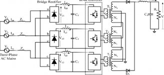
Sir, please note that a PFC (Vienna rectifier) is a boost converter and cannot be used to step-down, placing your minimum DC output around 600V or so (usually 700-750V). On the other hand, anything that operates at such power surely cannot skip the PFC function, as it would otherwise be drawing significant amounts of harmonic power from the grid.
Nevertheless, at home, you may safely feed an active PFC front-end fed from a 3-phase transformer at 100V or so, to obtain both good power factor and a steady DC output without any large capacitors. But the current sensors for PFC operation need to be inserted at the input of the transformer (rather than that of the rectifier, see picture), so as to include the transformer leakage inductances (both pri and sec) inside the current loop. Besides, by cleverly using a split bobbin winding (to control leakage), you could also integrate the PFC inductors into the transformer (as done in a resonant converter). Still, the modulation of a 3-phase PFC usually requires vector calculations (microcontrollers, programming) and could get too complicated for home experimentation. One may start on a simulator such as SPICE or Simulink to get a "feel" of things.
A 12-pulse rectifier can theoretically cancel all harmonics of order 2n (even), 3n (triplen) and 6n±1 (for n=odd), which means that the lowest harmonic in the input current waveform would then be the 11th (pf > 0.9 easily).

Dave Zan said:Sure, I have some 3 phase experience but not in the SMPS area so I am keen to learn.
Sir, please note that a PFC (Vienna rectifier) is a boost converter and cannot be used to step-down, placing your minimum DC output around 600V or so (usually 700-750V). On the other hand, anything that operates at such power surely cannot skip the PFC function, as it would otherwise be drawing significant amounts of harmonic power from the grid.
Nevertheless, at home, you may safely feed an active PFC front-end fed from a 3-phase transformer at 100V or so, to obtain both good power factor and a steady DC output without any large capacitors. But the current sensors for PFC operation need to be inserted at the input of the transformer (rather than that of the rectifier, see picture), so as to include the transformer leakage inductances (both pri and sec) inside the current loop. Besides, by cleverly using a split bobbin winding (to control leakage), you could also integrate the PFC inductors into the transformer (as done in a resonant converter). Still, the modulation of a 3-phase PFC usually requires vector calculations (microcontrollers, programming) and could get too complicated for home experimentation. One may start on a simulator such as SPICE or Simulink to get a "feel" of things.
A 12-pulse rectifier can theoretically cancel all harmonics of order 2n (even), 3n (triplen) and 6n±1 (for n=odd), which means that the lowest harmonic in the input current waveform would then be the 11th (pf > 0.9 easily).
Last edited:
A typical 100W/8Ω transistor amp needs ±rails of 28V. Your 350V 4,000µ capacitor equates to ~50,000µF at 28V. Whether a doubling to 100,000µF would provide a noticeable improvement depends on external factors including the demands of the loudspeakers connected and the acuity of the listener.I find a similar result with my tube amp builds. In my case using large caps allows smaller R in the filters. But only to the point of diminishing returns. I've never used more than 4000uF which I used in a 100W amp. B+ was 320V.
I use 72,000uF in a 5W SE source follower amp (loaded by 300W light bulbs and inspired by the De-Lite amp by Nelson Pass, ~70V rail) but that's mainly because the PSRR isn't very good. 😀
Hi I tried to find the stuff without bulk/filter capacitors...
"Therefore, there is no
conceptual reason, why the constant
instantaneous three-phase input power
could not be converted directly into a
constant DC output power. The obvious
added advantage is that such AC/DC
conversion will completely eliminate need
for energy storage"
Quoted from https://www.power-mag.com/pdf/issuearchive/46.pdf, where he explains how the concept is implemented in practice.
Please explain what elimination of capacitors would [achieve] except cost cut...
Lower cost for the same performance isn't sufficient?
Ok, add simplicity, efficiency, reliability from less components to fail, environmental benefits from less junk at end-of-life?
More compact, less massive, for cases where these matter.
More important in my case would be satisfaction at a neat solution rather than a clumsy one with unnecessary parts.
A 3 phase transformer followed by the classic rectifier/bulk cap combo
It's a possibility, simple and reliable, obviousness has its benefits.
...I find it hard... 16A and 32A non interchangeable
Yes, the CEE system is not as smart as the Australian.
A lower current connector will fit into a socket able to power it.
A connector will not fit into a socket of lower capacity, to prevent overload.
(it's not totally inter-compatible however)
...at least do it properly: 3 center-tapped transformers and a 6-phase mercury arc rectifier...😉
+1 on the 😉
... to the point of ridiculousness.
...only needs 20,000µF or so based on electrical analysis, so why does one with 40,000µF sound better? And why does one with 80,000µF sound better than that, and one with 160,000µF sound even better??
And 320,000 µF even better???
And 640,000...
And...
Any decent amp should have sufficient power supply rejection for this not to be audible.
So I'd suspect expectation bias too, unless the amp is quite defective.
Of course, solid data beats mere suspicion, so - test protocol? sample size? repeatability? confidence level?
Best wishes
David
Last edited:
Well I read it and it has some demands and still has a bulk capacitor in the (conceptual) schematic. It gave the impression it all is meant for solar and electric vehicle chargers where the focus is on efficiency at relatively constant high power. Maybe 400 V DC bus voltage is not that OK for a power amplifier. A tube amplifier would love it but then the load is not in Amperes 🙂 Maybe it would make matters more clear if you could tell what kind of amplifier and its supply voltages you are after. Symmetric, asymmetric etc.
In high power applications high voltage DC bulk capacitors are chosen for reliability and replaced (in my branch) after 50.000 hours of continuous load. I do admit I have seen exploded ones but only so after either a bad batch or let's say inappropriate use of the devices but then the IGBT's also are gone.
In high power applications high voltage DC bulk capacitors are chosen for reliability and replaced (in my branch) after 50.000 hours of continuous load. I do admit I have seen exploded ones but only so after either a bad batch or let's say inappropriate use of the devices but then the IGBT's also are gone.
Last edited:
Nevertheless, at home, you may safely feed an active PFC front-end fed from a 3-phase transformer at 100V...
I need about +-100 V so I see several practical options.
First is kind of obvious, a 3 phase rectifier to power the usual SMPS DC drive circuitry for a hi-frequency transformer for step down and isolation.
Needs only small filter capacitor on output.
May not even need PFC, dependent on the transformer driver.
Second, the Cuk rectifierless circuit, very small resonant capacitors on the mains side.
Third is not SMPS, just simple transformer, rectifier and capacitor.
Fourth is delta + Y transformer and 12 pulse rectifier and capacitor.
Lower ripple for a particular capacitance than third option.
Best wishes
David
- Home
- Amplifiers
- Power Supplies
- 3 phase power supply for audio !