In a similar spot, getting going in this project and need to source a pulley for a 12" VPI platter. Would like to get one made per Bill's drawing to run 2-3 belts. I'll take a look at emachine shop or similar and would be willing to front getting a batch of 10 or so made if the quality is up to spec.
Thanks! One user tried the 0.75” pulley from sdp-si
Product | Designatronics Store | Stock Drive Products/Sterling Instrument
I think the 3mm VPI belt would be fine with the slightly shorter diameter and the 1/8” pulley groove. If there isn’t an option from SOTA or can’t find a shop, is this a reasonable backup?
It looks interesting. With a center bore of 0.2498" it might be an interference fit, although the AA shaft spec is +0.0000/-0.0005.
Might be worth a try. Did the other user report their results?
Regarding the 4mm 3/16” adapter sleeve, would this only work with a pulley with a set screw? I have a HW-19 with the long pulley and interference fit - no screw.
Trying a different tack, how true would a coupler and extension shaft be if I chose a different pulley? In other words, is there a chance the pulley would wobble? Or are the tolerances tight enough to make this a viable option?
Trying a different tack, how true would a coupler and extension shaft be if I chose a different pulley? In other words, is there a chance the pulley would wobble? Or are the tolerances tight enough to make this a viable option?
Any time you add another tolerance into the equation it can affect the result. The adapters are cheap; try it and see if it works. The fact that your pulley is a tight fit reduces some of the tolerance.
As far as the set screw, you will need to secure the adapter to the shaft; maybe non-permanent glue?
As far as the set screw, you will need to secure the adapter to the shaft; maybe non-permanent glue?
Hello,
After exchanging knowledge with the respectable member Pyramid here i knew which dimensions to get for my pulley.
At first Sota offered me to machine a special diameter pulley at additional cost because i am using a bigger platter. Because the motor unit came from them my initial thought was to ask them for the pulley to get one with the right tolerance. BUT it took such a long time that they offered a refund.
I worked in '' metal business '' so i should have known that if you ask a well equipped company to make a pulley it would be a piece of cake.
It took some time to find a company in my vicinity willing to make two slightly different diameter pulleys because usually they are making bigger series.
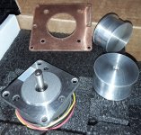
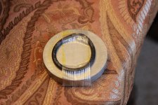
The idea of making a hole in the center and use a little screw to secure the pulley to the motor ax was quickly abandoned .
My idea was to go for a tight fit ( not one that will need force to install it!) because i choose to get one pulley for a rubber belt and one for a mylar tape.
Because the contact area between ax and pulley is 6.35 mm diameter and 19 mm long there is no need for a strong bonding agent. I have one product so far that i wanna try. I think it should be as liquid as sewing machine oil to get a uniform thickness allover the contact area. On the upper side of the pulley there is an M5 threaded hole to be able to use a M5 bolt to '' break '' the connection between ax and pulley.
Of course using '' real glue '' would give to much grip!!
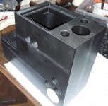
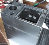
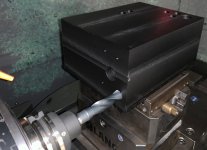
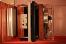
On the photos you can also see my POM material motor housing. Under the motor itself there is a big cavity filled with lead shot.
There are some round deep cavities filled with lead shot too and closed with some foam because POM is almost impossible to glue.
Greetings, Eduard
After exchanging knowledge with the respectable member Pyramid here i knew which dimensions to get for my pulley.
At first Sota offered me to machine a special diameter pulley at additional cost because i am using a bigger platter. Because the motor unit came from them my initial thought was to ask them for the pulley to get one with the right tolerance. BUT it took such a long time that they offered a refund.
I worked in '' metal business '' so i should have known that if you ask a well equipped company to make a pulley it would be a piece of cake.
It took some time to find a company in my vicinity willing to make two slightly different diameter pulleys because usually they are making bigger series.
The idea of making a hole in the center and use a little screw to secure the pulley to the motor ax was quickly abandoned .
My idea was to go for a tight fit ( not one that will need force to install it!) because i choose to get one pulley for a rubber belt and one for a mylar tape.
Because the contact area between ax and pulley is 6.35 mm diameter and 19 mm long there is no need for a strong bonding agent. I have one product so far that i wanna try. I think it should be as liquid as sewing machine oil to get a uniform thickness allover the contact area. On the upper side of the pulley there is an M5 threaded hole to be able to use a M5 bolt to '' break '' the connection between ax and pulley.
Of course using '' real glue '' would give to much grip!!
On the photos you can also see my POM material motor housing. Under the motor itself there is a big cavity filled with lead shot.
There are some round deep cavities filled with lead shot too and closed with some foam because POM is almost impossible to glue.
Greetings, Eduard
Attachments
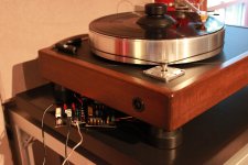
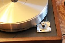
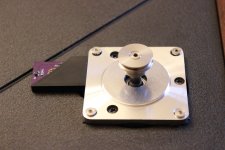
Had a little time this weekend so I test fit the motor into the VPI Classic. Have not seen any pictures of the Classic, so figured I'd share.
Few Notes:
- This is the 0.75” pulley from sdp-si, fits the motor shaft perfectly.
- Just a test fit with the screws, but you can see the slight difference in hole pattern. Will either pickup some other 6-32 low profile screws or attempt to counter sink/bore for final mounting. Maybe try to come up with an alternative trim ring once I finalize the tach mounting.
Question:
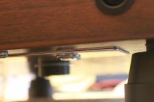
1 - This is mounted direct to the deck, as was the Hurst motor with the little trim ring. The hurst motor also had this little spacer with o-ring (see pic) below it. Any recommendations on further damping between the motor/deck? I don't have any vibration instrumentation, but put the needle on the table/album without the belt attached, but motor running and could not perceive any difference in sound.
Few Notes:
- This is the 0.75” pulley from sdp-si, fits the motor shaft perfectly.
- Just a test fit with the screws, but you can see the slight difference in hole pattern. Will either pickup some other 6-32 low profile screws or attempt to counter sink/bore for final mounting. Maybe try to come up with an alternative trim ring once I finalize the tach mounting.
Question:
1 - This is mounted direct to the deck, as was the Hurst motor with the little trim ring. The hurst motor also had this little spacer with o-ring (see pic) below it. Any recommendations on further damping between the motor/deck? I don't have any vibration instrumentation, but put the needle on the table/album without the belt attached, but motor running and could not perceive any difference in sound.
Attachments


Hi! A quick question - how much current headroom remains when using the 15V / 1A supply powering both boards? I would like to see how much I have left for various and sundry additions. I am using the BLWS231S-24V-2000.
I just measured total current at ~700mA at start up and <500mA with reduce voltage during operation.
Total current = SG4+MA3D.
Thank you! I am going to use a Meanwell RS-15-15 and will have plenty of current to work with then.
Successful Build!
First of all, huge thank you to Pyramid and Seth Hensel for making this project available to our DIYAudio community. I just completed a build using the SG4 and MA-3D to drive an AA BLWR motor and had zero issues. The BLWR motor had a VERY small amount of vibration that I was able to reduce even further by holding the motor in my hand and adjusting phase with the SG4 as well as very small tweaks using the trim pots on the MA-3D.
I also designed and 3D printed a quick PCB mount for both the SG4 and MA-3D I thought I'd share with you guys as well. My intent is to hot glue the printed PCB mount into the enclosure I'm working on but the boards are fastened with some tiny 1-64 screws I had laying around from some other Arduino project.
You can print this and then drill out the holes for whatever size screw you have around. Hope this tiny contribution to this project helps!
Attachments

I want to experiment using Steve Cobham's Zeus controller to drive one of the AA motors. I'm trying to decide if the Zeus will have sufficient output current to drive the motor without an additional class D amp. Can anyone tell me the current that the BLWR motor draws when operated at 4.1 Vrms (the output of the MA-3D)? I think the Zeus controller will output about 2 watts, but I need to verify.
The AA motors are 3 phase, I believe the Zeus controller is only 2 phase?
The power consumption at start up is ~12W; during normal operation (reduced voltage) the power consumption is ~9W.
The power consumption at start up is ~12W; during normal operation (reduced voltage) the power consumption is ~9W.
Thanks for the information Bill. Just what I needed. The basic Zeus is 2 phase but you can link 2 Zeus drives for 3 phase and the software does support that.
Capacitor polarity variance between schematic and board
I am building my 4th MA3D and just noticed what might be a discrepancy between the schematic and board.
The following capacitors seem to have reversed polarity between the schematic and board: C5, C6; C9; C11.
I'm assuming the polarity on the board is correct because I have built 3 according to the polarity on the board.
What am I missing?
The schematic does not show polarity which would have a '+' indicator; the shape of the part does not denote polarity as the same shape is used for non-polarized caps.
The 3 input caps for the 3 signal phases can sometimes be backward from the silk screen on the PCB depending on the DC voltage on the input. If in doubt, look at both sides of the cap with a DC voltmeter and reverse them if the voltage on the chip amp side is greater than the input side.
The 3 input caps for the 3 signal phases can sometimes be backward from the silk screen on the PCB depending on the DC voltage on the input. If in doubt, look at both sides of the cap with a DC voltmeter and reverse them if the voltage on the chip amp side is greater than the input side.
Thanks, Bill. That makes sense. I've just been sensitized to it while repairing an old McIntosh tuner. The silkscreen was reversed from the schematic. Thanks for the tip about the input caps.
I just checked. All 3 input caps (C5, C6, and C11) show about 0.6VDC on the input side (marked positive on the silkscreen) and about 1.8vdc on the chip amp side. I suppose I should reverse these caps.
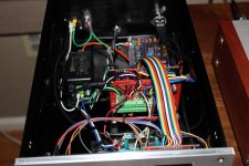
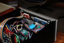
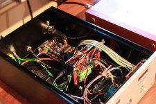
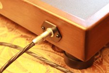
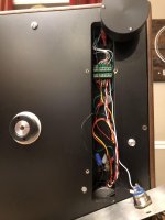
Wanted to post a thank you to Bill for this wonderful project. The SG4 and BA3 amp work perfectly. Had a few bugs with my Arduino tach, but they are sorted now. Fun Project, thanks again! Not many pics I could find where anyone retrofit everything into a Classic, so here you go! Still want to go to a 3 belt setup.
Attachments
-
 IMG_7872 (Large).JPG225.3 KB · Views: 211
 -
 IMG_7882 (Large).JPG294.4 KB · Views: 209
 -
 IMG_7881 (Large).JPG271.9 KB · Views: 210
 -
 IMG_7878 (Large).JPG364.2 KB · Views: 204
 -
 IMG_7875 (Large).JPG297.1 KB · Views: 233
 -
 IMG_7876 (Large).JPG266.3 KB · Views: 275
 -
 IMG_7870 (Large).JPG340.8 KB · Views: 287
 -
 IMG_7885 (Large).JPG327.3 KB · Views: 269
 -
 IMG_7884 (Large).JPG322.4 KB · Views: 265
 -
 unnamed (Large).jpg229.6 KB · Views: 202
- Home
- Source & Line
- Analogue Source
- 3 Phase Class D amp for DIY BLDC motor Drive