Thank you. It’s worm, but not hot in my setup. I feel about 40 C by finger (not measured). It is way less than spec max and so, I can leave it as is without extra heat deception.
Hello,
I got myself the Sota eclipse package and Sota told me they could make a bigger pulley at extra cost (75 $) Already got the motor because i wanted to have a POM material motor housing machined at a nearby "" plastics company" where they have 5 axis machine centres.
Pulley has not been made yet . I asked sales for a drawing so i can have it machined closeby. BUT sales at Sota have to ask engineering if they can give to me.
The famous member Pyramid gave me the diameter i needed. I know it has to be a crowned pulley. I thknk the average height of a belt is 4 to 5 mm.
It seems the crowns " shape " usually isnt that important.
Pyramid gave me the diameter of 19,035 millimeter. If we take a pulley with a height of around 25,4 mm ( 1inch) i could ask the company to make the smaller diameter 17 mm at both ends and then grow bigger towards the center. Good idea or does the area where the belt will run be more like a round shape.
Once i saw some info on pulley material. This company sells many different kind of plastics but can also have it machined from most kind of metal i think by another company.
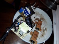
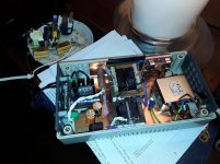
Because Sota send me a supply for 120 volts 60 cps i decided to use corona time to make my own from the part box.
On the plate with the test resistors are the old ones with 6 feet cables. Mine are less than one feet for sure.
Greetings,Eduard
I got myself the Sota eclipse package and Sota told me they could make a bigger pulley at extra cost (75 $) Already got the motor because i wanted to have a POM material motor housing machined at a nearby "" plastics company" where they have 5 axis machine centres.
Pulley has not been made yet . I asked sales for a drawing so i can have it machined closeby. BUT sales at Sota have to ask engineering if they can give to me.
The famous member Pyramid gave me the diameter i needed. I know it has to be a crowned pulley. I thknk the average height of a belt is 4 to 5 mm.
It seems the crowns " shape " usually isnt that important.
Pyramid gave me the diameter of 19,035 millimeter. If we take a pulley with a height of around 25,4 mm ( 1inch) i could ask the company to make the smaller diameter 17 mm at both ends and then grow bigger towards the center. Good idea or does the area where the belt will run be more like a round shape.
Once i saw some info on pulley material. This company sells many different kind of plastics but can also have it machined from most kind of metal i think by another company.
Because Sota send me a supply for 120 volts 60 cps i decided to use corona time to make my own from the part box.
On the plate with the test resistors are the old ones with 6 feet cables. Mine are less than one feet for sure.
Greetings,Eduard
Attachments
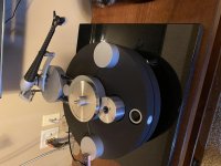
Motor case is ready and motor is in. Pulley must go back for some fix. I made mistake with its height and we made it too tall. So, if some of you have Wilson Benesch Circle One turntable, and you want to upgrade with for new motor, then I can share with all my final drawings.
Attachments

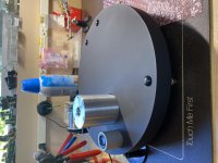
Got all tested today (PSU controller is not boxed yet). It is fine, but my speed is not in the range that I targeted. It is fluctuates between 33.320 and 33.350. Each revolution creates random up and down jump. I probably know the reason and it is related to my two belts (o-rings) wobble on sub-platter side-wall. I see that by eye. Is that common practice to make these tinny grooves on sub-platter, same way as I see VPI platter has?
Attachments

I have built for SG4/MA3D combinations driving Anaheim Automation motors - 2 BLWS and 2 BLWR. It's a great project and I appreciate the efforts that Pyramid put into the design and the ongoing support.
I am having a problem with one of the BLWS motors. About half the time it starts in reverse and the other half it starts correctly. I've checked the balance on the output voltage and it seems to be fine. It turns at the correct speed when it's rotating in the correct direction and stays stable. I haven't checked speed when running in reverse but am guessing it's stable also.
I'm driving the motor with about 18.8 Hz to get the correct speed at 33.33 rpm. I wonder if this low frequency is causing the problem. I seem to recall reading that anything below 20 Hz can present a problem, but I can't find where I read that. So it might be a figment of my imagination. Any suggestions will be most appreciated.
Does the BLWS motor that starts in rev, behave the same way on the other amps/SG4 combos? Does the BLWS motor that works correctly run backward on the amp/SG4 that runs backward with the other motor?
Are the phases of the SG4 at factory default (120 & 240)? Does adjust them up or down cure the problem or make it worse?
Are the phases of the SG4 at factory default (120 & 240)? Does adjust them up or down cure the problem or make it worse?
The phases are set at factory level. Thanks for the other suggestions. I'll investigate and report back.
Just trying to connect info that might be interesting to some of you who is using BLWR172S-24-2000 motors (I assume that BLWS will behave in the same way). "We", as a team where 99.9% is done by robnik33, succeed to make Tachometer to work with PID to support 20/27Hz setup with BLWR motor (300RPM of pully). Speed correction is done as feed forward.
Thread: Digital Tachometer for record player (LCD display)
Arduino sketch for 20Hz is attached. Please note that you might need to modify it for you type of display and for your target speed.
Thread: Digital Tachometer for record player (LCD display)
Arduino sketch for 20Hz is attached. Please note that you might need to modify it for you type of display and for your target speed.
Attachments
Last edited by a moderator:
While not related to the above conversation, I have a question regarding power supplies for this DC motor drive systems.
Given the stability of the current setup with a generic wallwart DC adapter, is there any benefit in upgrading the power supply unit to something a bit more sophisticated? I have been curious about trying the IFI iPower+ power supply for my Class D/ SG4 unit, but wanted to get some input before doing so.
Given the stability of the current setup with a generic wallwart DC adapter, is there any benefit in upgrading the power supply unit to something a bit more sophisticated? I have been curious about trying the IFI iPower+ power supply for my Class D/ SG4 unit, but wanted to get some input before doing so.
I have a question about aligning the MA3D. Following the procedure I set the output for each phase to 4.200 Vrms. I can get them all very close. When I adjust based on voltage at the test point, these individual voltages vary - for example 4.185, 4.200 and 4.225. I'm curious why this might be. Thanks.
It's not uncommon for the voltages to off by 10-30mV per phase. Are you measuring the 4.2VAC at the output to the motor or prior to the inductors (at the output of the amps)?
Also, make sure the phases are at 120 & 240 (0° is not adjustable). If you adjust the phases for lowest vibration, they will not sum to zero with the same levels.
The phase accumulator uses an 8 bit offset for 90, 120 and 240. 256/4 gives an integer result for 90°. 256/3 does not so there is some rounding error (119.53125° and 240.46875° actual).
Last edited:
Measuring at the output to the motor.
Also I'm continuing to have a voltage stability problem. Originally phase 0 wasn't stable so I replaced the TPA3125 amp and now the voltage instability is phase 120. I guess I'll try a new amp chip.
Also I'm continuing to have a voltage stability problem. Originally phase 0 wasn't stable so I replaced the TPA3125 amp and now the voltage instability is phase 120. I guess I'll try a new amp chip.
This is a shared DIY project for non-commercial use.
The MA-3D is a 3 channel class D amp suitable for driving a BLWR172S-24-2000 or BLWS231S-24-2000 BLDC motor from Anaheim Automation. The amp is custom designed to work with only these 2 motors; any other motor connected to the output of the amp can permanently damage the amp. The BLWR series has a 4mm shaft and no mounting flange. The BLWS series has a ¼” shaft and a mounting flange that matches up with a Hurst 59 series motor. There are aluminum sleeves available from the RC boat market that will convert 4mm shafts to 3/16" props that will allow the BLWR series motor to work with 3/16" center bore pulleys ie VPI 600 RPM pulleys.
For an existing VPI Aries 2 motor pod, would you suggest the BLWR plus aluminum sleeve and the VPI 600 rpm pulley?
I think the motor might be too tall to fit in the VPI pod; check with the data sheet at Anaheim Automation web site.
The BLWS series motor has a mounting flange that is (almost) a drop in replacement for the Hurst motor. The flange is thicker and the mounting holes are within 0.040" on center with the Hurst.
The BLWS series motor has a mounting flange that is (almost) a drop in replacement for the Hurst motor. The flange is thicker and the mounting holes are within 0.040" on center with the Hurst.
Yes, you are correct. I assume the 12v BLWR171S isn’t an option, or the 1/4” shaft can’t be custom ordered with 4mm shaft? I am glad you mentioned to check!
Custom shaft sizes are a possibility, but they will have minimum order requirements (100 pcs or more). You would have to have a custom pulley made; I think some people on DIYAudio have done this, maybe they can help you source one.
SOTA uses a similar motor on their Total Eclipse package; maybe they could sell you a pulley?
SOTA uses a similar motor on their Total Eclipse package; maybe they could sell you a pulley?
I made my pulley at local mechine shope and they charged me $80, and that is include brass material.
Custom shaft sizes are a possibility, but they will have minimum order requirements (100 pcs or more). You would have to have a custom pulley made; I think some people on DIYAudio have done this, maybe they can help you source one.
SOTA uses a similar motor on their Total Eclipse package; maybe they could sell you a pulley?
Thanks! One user tried the 0.75” pulley from sdp-si
Product | Designatronics Store | Stock Drive Products/Sterling Instrument
I think the 3mm VPI belt would be fine with the slightly shorter diameter and the 1/8” pulley groove. If there isn’t an option from SOTA or can’t find a shop, is this a reasonable backup?
- Home
- Source & Line
- Analogue Source
- 3 Phase Class D amp for DIY BLDC motor Drive