The housing for the motor you made - is it for simply mounting purposes or does it have a heat sinking capacity, also. Does one need to come up with some kind of heat sinking for the motor? I know you said the things can get quite hot.
The resistors specified require getting 200 of them - not that that is expensive but certainly a waste.
May I assume there is nothing special about those resistors? I figure garden variety metal films would do just as well?
Thanks,
The resistors specified require getting 200 of them - not that that is expensive but certainly a waste.
May I assume there is nothing special about those resistors? I figure garden variety metal films would do just as well?
Thanks,
The case does add some heat sink capability. A metal bracket would more than likely be sufficient.
They used to sell the resistors in one-off qtys. Any metal film 1/8W resistor will work.
They used to sell the resistors in one-off qtys. Any metal film 1/8W resistor will work.
I've built a couple of custom tables using the BLWR motor and a VPI platter/bearing. The most recent one is noticeably noisy. I think it is a bearing noise and does not lessen appreciably when the motor is mounted to the plinth. The noise is not being transmitted to the tonearm or the amplification. I've tried replacing the bearings according to a couple suggestions from earlier in this thread but they actually made it worse. I wonder if I'm using an incorrect bearing. If anyone has successfully replaced the bearings and can suggest a source, I would be very appreciative.
I have not gone through the thread, just point me to details of the bearings used.
You could try a stiffer grease in the existing bearings...wheel bearing grease, front axle grease...
You could try a stiffer grease in the existing bearings...wheel bearing grease, front axle grease...
I am hoping those who are using the 4 mm shaft motor and still keeping up with the thread would tell what they are using for a pulley on the motor.
I figure I will have to get one made but my curiosity got the best of me.
Found this piece which will be good to get started with:
3401 Series Set Screw Round Belt Pulley (4mm Bore, 16mm PD) - goBILDA
Should make it very easy to align the LENCO idler wheel.
Wish there were two set screws but then this is temporary.
Take care,
SNAP!
I just received a couple of those 3401 pulleys from goBILDA
Seems pretty hard to source an off the shelf solution 4mm .
These pulleys seem well machined and fitted on the shaft without any play
(I cant test it yet as I'm not finished the electronics)
If you are going to get a custom made pulley, especially if it has 2 grooves, I'd be interested.
Guess the motor housing?
I am hoping those who are using the 4 mm shaft motor and still keeping up with the thread would tell what they are using for a pulley on the motor.
I figure I will have to get one made but my curiosity got the best of me.
Found this piece which will be good to get started with:
3401 Series Set Screw Round Belt Pulley (4mm Bore, 16mm PD) - goBILDA
Should make it very easy to align the LENCO idler wheel.
Wish there were two set screws but then this is temporary.
Take care,
I'm following this with interest. I've built several lenco customtables and would like to try the Anaheim Automation motor. Can you share a photo of the mounting scheme? Thanks.
I am still waiting for my PCBs from the fabricator. And my pulleys.
At this point one has to say there could not be a better way to handle custom PCBs than what Mr. Carlin does. Ordering was simplicity itself. Just anxiously awaiting. I figure I have one week to go.
Have my parts. Got the motor which is a jewel.
I figure the fellow who supplies the programmed EPROM is on a vacation since I have yet to hear from him. It is that time of the year.
For mounting - of course, this is not attached to the plinth or top plate - I am waiting for this heatsink to arrive

I figure I will place this within a length of aluminum channel - have to get the heat sink to know what size would work best and which way to orient the channel. Plenty easy to do.
You got those pulleys faster than I - I assume you discovered them for yourself well before I made my post.
I do not recognize what you are using for a housing.
Always good to have an accomplice in these adventures.
Did not expect that image to be so large - I have no idea how to make it smaller.
Needless to say the fan will not be used.
Take care. (and thanks to the fine fellow who makes this possible)
At this point one has to say there could not be a better way to handle custom PCBs than what Mr. Carlin does. Ordering was simplicity itself. Just anxiously awaiting. I figure I have one week to go.
Have my parts. Got the motor which is a jewel.
I figure the fellow who supplies the programmed EPROM is on a vacation since I have yet to hear from him. It is that time of the year.
For mounting - of course, this is not attached to the plinth or top plate - I am waiting for this heatsink to arrive
I figure I will place this within a length of aluminum channel - have to get the heat sink to know what size would work best and which way to orient the channel. Plenty easy to do.
You got those pulleys faster than I - I assume you discovered them for yourself well before I made my post.
I do not recognize what you are using for a housing.
Always good to have an accomplice in these adventures.
Did not expect that image to be so large - I have no idea how to make it smaller.
Needless to say the fan will not be used.
Take care. (and thanks to the fine fellow who makes this possible)
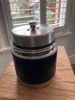
Is that a soup thermos!? LOL! That's kind of hilarious, and also kind of awesome!Here it is
The picture is distorted.
Easier to see it here: https://www.amazon.com/gp/product/B00LXCLEXQ/ref=ppx_yo_dt_b_asin_title_o00_s00?ie=UTF8&psc=1
Easier to see it here: https://www.amazon.com/gp/product/B00LXCLEXQ/ref=ppx_yo_dt_b_asin_title_o00_s00?ie=UTF8&psc=1
Here's my take on the Lenco motor drive.
The BLWR motor will fit inside the lenco motor housing (needs a small mounting plate). The retains the alignment and motor isolation.
The BLWR has a 4mm shaft. I will install a .25" shaft over the motor shaft. This will drive the idler wheel in the same configuration as standard Lenco. The idler is 2.56" diameter. Driven by a .25" shaft on the motor at 600 rpm will have the idler rotating about 58.5 rpm. If this idler is positioned about 4.5" from the center of the platter, the platter will rotate about 33.33 rpm. The SG4/MA3 will drive the motor and allow fine tuning to compensate for inexactness in the location of the idler or measurement of idler diameter. I think it's within the pecs for the SG4/MA3D setup.
Of course this is still theoretical and yet to be tried but I thought I'd lay out my thoughts to see if I have any errors in my thinking.
You are braver than I to attempt to get the motor to work in the original motor's location!
I do not not want to deal with those springs! My heavier springs suspending the plinth are much easier to adjust!
I had moved the motor from the plinth years ago and hear enough reasons to keep it there even though it does introduce problems that I am hoping the Carlin system will minimize.
Got my heat sink in today and it is nicely done - and got the pulleys. I got three in case there was any variation in them Left the motor at home so am not able to play around with it, yet.
Everyday I look at my DIYAudio message box in hopes of seeing a note from the EPROM fellow.
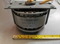
I saw the photo of the heatsink you are using to mount the motor. How is the motor held in the heatsink? How is the motor assembly held in the chassis? A photo or two would be great.
The heat sink slips over the motor. It is only slightly longer than the motor. The part where the fan was will be on the bottom.
I had to bend it a bit to get it tight - I will use some thermal goo when I mate them for final assembly.
The plan is to use 4 inches wide aluminum channel and then find a good way to secure the motor within the channel. Some kind of strap over the top using some 1/8 inch copper strips and then some copper on either side of the motor set it in the center. Along with a piece of copper bar on the bottom of the channel for positioning the motor and ballasting. Obvioulsy 4 inches in width will not work and the next choise i
The top of the pulley needs to be 3.25 inches from the base to meet the bottom of the idler. Got to get the channel to know how to proceed - ONLINEMETALS,COM is a good place to get all kinds of metals for these projects.
This could be a good ballast: RotoMetals Copper Chop Wire 99.99% Min
Looking forward to getting an idea of how concentric the pulley is, I got three and they all seemed to be about the same. I am going to try a sliver of copper foil opposite the set screw for a little more precise center. I wish the bore of the pulleys had been slightly smaller. Seems like the groove in the pulley will work well with the idler wheel.
I will post a picture of the motor within the heat sink Monday.
Is that a soup thermos!? LOL! That's kind of hilarious, and also kind of awesome!
Yes Correct
A chocolate cigar for you
It’s filled with lead & inc motor weight about 5kg so should be very stable.
Cost me $8 and it will suit my TT
The new issue of STEREOPHILE has an extraordinary turntable reviewed - a $450,000 dollars table that can cost over one-half million dollars if you add a few extras.
Thought it was interesting in that it is using what the manufacturer believes are the last forty NOS PAPST motors that I presume were the ones mentioned early on in this thread. Used for REVOX capstan motors - though i wondered if Fremer meant to say STUDER. In case anyone is wondering where the last few went ...
They are being powered by three FIFTY watts amplifiers! I can see Mr. Carlin shaking his head.
I would include the link but I guess it is not available online yet. An optimistic preview from Fremer's website: Air Force Zero Turntable Debuts: If You Have to Ask Price, You Can't Afford! | Analog Planet Only about $200,000. shy ...
Nonetheless, without full assaults on the art such as this we never move forward.

Very nice! Completely out of my range but I admire all true assaults on the art.
I would love to see what you use it for - any chance of elaboration?
I would love to see what you use it for - any chance of elaboration?
- Home
- Source & Line
- Analogue Source
- 3 Phase Class D amp for DIY BLDC motor Drive