...happen? oscillation bursts of course 😉...
So I think you might just try it. What could happen?
...
Just ordered some ferrite beads from pdf from post #2833 for testing.
Good that I own a spectrum analyser up to 2.1GHz to detect high frequency oscillation...
BR, Toni
I'm currently planning a new monster green amp (SA2019) with those specs:
+/- 85V rails, +/- 20V rails
450W@8R,900W@4R,1600W@2R
Idle power dissipation ~ 20W
The outer rails are driven by 8 pairs IRFP240/9240. To hold the gate resistance low I plan to add ferrite beads and like to ask you if you have experience using ferrite beads like the attached one.
BR, Toni
Hi Toni,
why do you need 1000 watts? 100W are completely sufficient. 200W is almost an overkill. Mostly you hear music with a few watts.
My problem with ferrites is they are often not resistive enough for what I want. However I have fixed this by just using them as small inductors, paralleled by resistors.
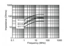
Years ago I bought some Bourns FB-73 series ferrite beads, which according to the datasheet appear to be nicely resistive above 10MHz with reasonably high inductance. They went obsolete and it is hard to find similar beads. Here is something similar with DC bias info:
https://www.mouser.com/datasheet/2/150/2773019447-346321.pdf
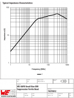
For an audio amp I think you are looking for high inductance and low resistance (like in the attached FB-73 chart), but most beads are intended for RF or SMPS use.
Years ago I bought some Bourns FB-73 series ferrite beads, which according to the datasheet appear to be nicely resistive above 10MHz with reasonably high inductance. They went obsolete and it is hard to find similar beads. Here is something similar with DC bias info:
https://www.mouser.com/datasheet/2/150/2773019447-346321.pdf
For an audio amp I think you are looking for high inductance and low resistance (like in the attached FB-73 chart), but most beads are intended for RF or SMPS use.
Attachments
Dear keantoken,
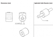
thx for reply. Your part is similar but needs to be soldered. I plan to use a gate resistor of 47R AND a through hole ferrite bead in series. Ferrite bead directly mounted at gate pin. This adds 30 - 60 ohm extra Z above 20MHz where the VMOS devices are prone to oscillation.
Gate DC current is very low so hopefully there is no Z reduction due to DC saturation.
Using IRFP240/9240 the gate resistor is usually kept higher as 100R to avoid oscillation. Bob Cordell has used 47R gate resistors and a zobel network from gate to ground using 39p in series with a 100R resistor.
(page 11 in http://www.cordellaudio.com/papers/MOSFET_Power_Amp.pdf)
I hope I can avoid this extra zobel if the ferrite bead works as desired.
Maybe Bob could add a comment?
EDIT: on page 12 of his PDF Bob talks about using a 10R gate resistor and ferrite bead and well shielded gate to driver connections instead of the zobel network.
BR, Toni
Attachments
Last edited:
... Ferrite bead directly mounted...
In my own class H vFET amp I have simulated with added ferrite beads - without much success, more difficult to improve the stability than I expected.
Perhaps you can find beads with a better combination of resistance and inductance values.
In the mean time I have started to think about Kelvin leads, used in RF circuitry to work around lead inductance.
Some of the IXYS vFETs are available in SOT227 format with Kelvin lead for the source.
Have you considered this possibility?
Best wishes
David
Using the "Kelvin lead" source connection of the SOT227 devices is good for ultra fast switching where we would have extremely high current pulses where the voltage drop could be significant. I don't think that we have this need in our linear "new class H" implementation to use kelvin lead source return for the driver circuit.
Of course it could help to stabilize where you have longer connections to the driver board using coax cable to shield the gate.
With paralleled devices it may be difficult to benefit from a kelvin lead source connection due to the current sharing source resistors.
Hopefully I have soon some time to solder a prototype for testing our class H design (or G design - the definitions of G versus H are unclear from author to author).
BR, Toni
SA2019 - Going green - New Class H
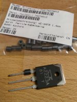
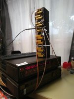
... yesterday got the ferrite beads for testing. Also the (high current, low reverse current) power schottky for lower rail voltage.
Attached image:
The ferrite bead fits well on a power transistor leg (only for upper rail MOSFETs; used a BJT just to test the through hole size).
BR, Toni
... yesterday got the ferrite beads for testing. Also the (high current, low reverse current) power schottky for lower rail voltage.
Attached image:
The ferrite bead fits well on a power transistor leg (only for upper rail MOSFETs; used a BJT just to test the through hole size).
BR, Toni
Attachments
Looks good. Very interested in you measurements and results! Are you just using it for the gates?
Yes, only the gates get a frequency dependent extra series resistance using this ferrite beads.
BR, Toni
BR, Toni
New test equipment - a keithley 238 SMU
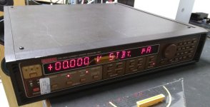
... had the chance to get a used but in good condition SMU unit from Keithley model 238 ...
The triax ports and cables are a nightmare when you look at the prices ... 😉
Need to manufacture DIY measurement cables ...
The first Linux 4.2.x GPIB tests where successful. Can read the version, set and read parameters and values ...
Combined with a relay board to switch between 10 devices it should be easy and funny to build a highest quality transistor matcher ... or curve tracer. The instrument can measure and deliver +/-110V or a current from fA to a maximum of 1A.
BR, Toni
Attachments
New test equipment - a keithley 236 and 238 SMU
BR, Toni
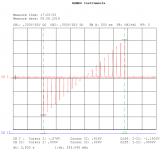
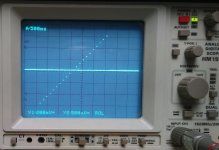
- had some time to create 6 Triax cables - that was a nightmare ... 😀
- had time to program a simple LinuxGpib perl script for testing linear sweep.
BR, Toni
Attachments
I finally have the astx running.
It's taken me a long time and it sounds nice.
Operating on ±48Vdc supply rails and biased to 510mA through the 3pair Lateral mosFET output stage.
The transformer is 240:4 * 34.5Vac for two isolated channels.
It will do 105W into 8ohms one channel driven and rises to 178W (-0.7dBW ref 8r) into 4ohms one channel driven.
I now have AndrewT's amplifier. It is an early version on the original boards.
I can vouch for it being a truly great music producer. The only change I would like would have been to case it in a larger case...it is a very tight fit which shows great skill in conceptualisation of space usage!!!
Thanks Brian for this information!
Yes, AndrewT (R.I.P.) has helped a lot during developiment of the ASTX amplifier series!
BR, Toni
Yes, AndrewT (R.I.P.) has helped a lot during developiment of the ASTX amplifier series!
BR, Toni
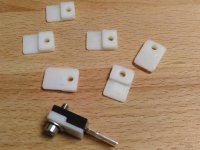
TOSHIBA TO200 mounting helper
Here a 3D STL file if you want to 3D print yourself this Toshiba TO220 mounting helpers.
You can adapt the STL in changing the dxf files and using the openSCAD script.
BR, Toni
Here a 3D STL file if you want to 3D print yourself this Toshiba TO220 mounting helpers.
You can adapt the STL in changing the dxf files and using the openSCAD script.
BR, Toni
Attachments
Toni, you deserve a gold star for your contribution to DIYAudio. I have nothing to give you, other than praise, you have it all imo, but I hope your health is #1.
P.S. Nice to see a Keithley with an Agilent cal tag 🙂
Cheers
Rick
P.S. Nice to see a Keithley with an Agilent cal tag 🙂
Cheers
Rick
Many thanks Rick for the kind words - I will give my best! 
Yes it's really funny to see a Agilent calibration tag on a Keithley ...
BTW: my health is so far OK, but the last months have had too less time for my hobby because of to much work...
So many projects waiting ... high performance 2StageEF Class H 1000W/8R, 1900W/4R
Have fun, Toni
Yes it's really funny to see a Agilent calibration tag on a Keithley ...
BTW: my health is so far OK, but the last months have had too less time for my hobby because of to much work...
So many projects waiting ... high performance 2StageEF Class H 1000W/8R, 1900W/4R
Have fun, Toni
Many thanks Rick for the kind words - I will give my best!
Yes it's really funny to see a Agilent calibration tag on a Keithley ...
BTW: my health is so far OK, but the last months have had too less time for my hobby because of to much work...
So many projects waiting ... high performance 2StageEF Class H 1000W/8R, 1900W/4R
Have fun, Toni
1000w/8R a real Monster! 😱
I will stay tuned. 😎
Many thanks Rick for the kind words - I will give my best!
Yes it's really funny to see a Agilent calibration tag on a Keithley ...
BTW: my health is so far OK, but the last months have had too less time for my hobby because of to much work...
So many projects waiting ... high performance 2StageEF Class H 1000W/8R, 1900W/4R
Have fun, Toni
You need for that +-90V=180V. No need for transformer anymore. Direct mains connection! 😀
- Home
- Amplifiers
- Solid State
- 2stageEF high performance class AB power amp / 200W8R / 400W4R