If case / heatsink height would be > 200mm (~ 5HE case size) e.g. heatsink size ~ 400x205x40 mm you are on the safe side.
BR, Toni
5HE !!!

Am I right? You bought the heatsink from cooltec. What color? silver? schaeffer did then the black finish?
Got them raw silver from cooltec. schaeffer has done m3 and m4 taping and afterwards anodizing.
BR, Toni
BR, Toni
If I remember correctly: one 3HE ct-400 was about 25 EUR and schaeffer about 120 EUR and 70 EUR for anodizing after machining. of course some transportation costs extra.
sorry! that was for both heatsinks...
you can download their "frontdesigner" and select "use own material" and you will get price for machining. anodizing afterwards is depending on the size of the parts and need to be asked for pricing individually per project. the quality is very high!
you can download their "frontdesigner" and select "use own material" and you will get price for machining. anodizing afterwards is depending on the size of the parts and need to be asked for pricing individually per project. the quality is very high!
Last edited:
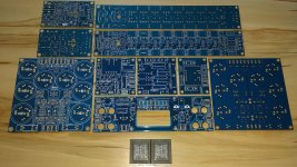
A giant amplifier!🙂A complete pcb set for a SA2014 dual mono build...
Another option is to use a tap that "forms" the threads rather than cuts them.
These work well in Aluminium, no chips and the tap is less likely to break, not weakened by chip clearance slots.
Should be available in your country or easy to send in a plain envelope for mail order.
Best wishes
David
Thought you guys might find this interesting. M5 form tapping aluminium @1200rpm. I can get thousands of threads from a single tap without breakage.
Currently I use OSG XPF taps, but have also had good results with DC-Swiss.
YouTube
Dear Mark,
thx for info! For DIY the needed rpm may be a little problem 😉
It would be nice if your team could do a manual test in 4 - 5 mm thick aluminium using a lion screw driver, if the lifetime of the form tap is overdue.
BR, Toni
thx for info! For DIY the needed rpm may be a little problem 😉
It would be nice if your team could do a manual test in 4 - 5 mm thick aluminium using a lion screw driver, if the lifetime of the form tap is overdue.
BR, Toni
It would be nice if your team could do a manual test in 4 - 5 mm thick aluminium using a lion screw driver
No problem. M3/4/5? Blind or through hole?
The main problem are the many M3 blind holes in heatsinks. A test with M3 blind + through hole would be a big help.
Thx in advance,
Toni
Thx in advance,
Toni
Hi Toni, first I want to say you have made a very nice and well engineered amplifier!
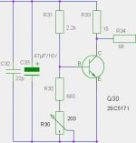
I have a question I haven't yet found any answer to, in the attached picture is a section of the Vbe multiplier of your amplifier, I wonder what is the function of R33, why don't we connect R34 to the upper side of R33?
I have a question I haven't yet found any answer to, in the attached picture is a section of the Vbe multiplier of your amplifier, I wonder what is the function of R33, why don't we connect R34 to the upper side of R33?
Attachments
A V-be is running with constant current source. Current change doesn't matter that much. Changing the rails from e.g. 60V to 50V changes the bias voltage +-4.4mV (with darlington configuration by +-1.8mV). Nevertheless I would not prefer the darlington config because you get then thermal issues.
Last edited:
Many thx! It is more or less also a community result based on the blameless amplifier from D. Self.Hi Toni, first I want to say you have made a very nice and well engineered amplifier!...
R33 makes the bias circuit more independent from bias current changes. (BTW: you are using the old schematics of SA2014; see index in post #1 for the latest SA2014 schematic)... I wonder what is the function of R33, why don't we connect R34 to the upper side of R33?
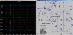
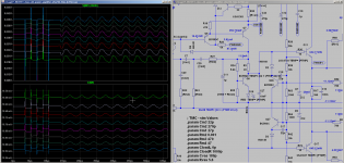
We have small bias current changes, because the constant current reference voltage source isn't fed with constant current. VAS constant current changes when rail voltages changes happen. Rail voltages are also dependent on AC voltage which is never constant over the day/hour/minute/second.
Attached 2 pictures to show the difference of BIAS voltage. With 22R bias resistor we have 20mV difference if we step the rail voltage from 35V to 56V and 27mV difference using 0.22R bias resistor.
Not much difference - only one of many details which makes the amp a bit more stable.
BR, Toni
Attachments
Last edited:
...
Nevertheless I would not prefer the darlington config because you get then thermal issues.
Which darlington config do you mean?
Thanks a lot Toni for your thorough reply explaining the function of the added resistor (R33) in the Vbe multiplier circuit!
Yes indeed the mains voltage can also affect the bias current through the Vbe in certain amplifier designs more susceptible to the mains variation, a valuable information also for those living in places where the mains voltage supply isn't very stable.
Very kind of you also running a few spice simulations for all of us to take part of, well appreciated.
Thanks also Pingrs for the Hagerman paper on an improved Vbe multiplier, good read.
Regards Michael
A test with M3 blind + through hole would be a big help.
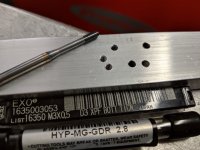
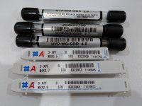
Tested the M3 form tap in a piece of 10mm thick 6061 flat bar.
Set the speed to max and the clutch to min. Tapping went well, with the tap bottoming in the hole and the clutch slipping without tool breakage. Backed out full speed no problems. 10mm through hole no problem either. For lubricant I used "Tap Magic" but I'd say any lubricant would be fine.
The first few holes were drilled freehand, the last 2 (on the left) were done in a drill press. As you can see, the ones using the drill press gave a much better result. Due to the fact that the drill size is only .2mm smaller than the tap, any amount of wondering with the drill leaves you with no material to form the thread.
Bottom line: As long as you use a drill press for the holes and have an adjustable clutch, the form tap is very successful using a cordless drill.
I'm sending a "Care Package" to Toni with M3,4,5 taps and suitable drills.
PS: Note the made in Austria welder in the background 😉
Attachments
- Home
- Amplifiers
- Solid State
- 2stageEF high performance class AB power amp / 200W8R / 400W4R