![WP_20161206_004[1].jpg](/community/data/attachments/541/541876-b98ecefd127cffab5dd25ea15ddf8e85.jpg?hash=uY7O_RJ8_6)
![WP_20161206_005[1].jpg](/community/data/attachments/541/541891-d638db4fbc8c1049442fba5183669333.jpg?hash=1jjbT7yMEE)
![WP_20161206_006[1].jpg](/community/data/attachments/541/541904-ec9b512e06bf28c9c992a2606f9c1630.jpg?hash=7JtRLga_KM)
I believe I wired correctly, see attached pics.
Attachments
![WP_20161206_007[1].jpg](/community/data/attachments/541/541918-70d35a75ca27ee7b538c1cc78b424248.jpg?hash=cNNadcon7n)
Last edited:
Thanks to all for the help. I will try all the options and see what I get.
Thomas; your timely post has saved me asking those questions!
Apart from the sibilance issue I have (which may or may not be related!), the #26 pre does seem to allow more of the music through than anything I have owned previously. So those scope shots were a bit of a shock! All your replies have helped my understanding of what to expect from a transformer coupled output. Using a scope is new to me; a little knowledge is a dangerous thing, eh? 😕
At the moment I am very low on energy, so it may take me a little while to work through the tests.
Richard.
(I thought I had better add my name, so you don't have to keep calling me awkward! 😀)
In reply to #4084:
You use a lot of solder...
But it seems to be wired for Alt S.
The best you can do is unsolder the B+, plate connection and secondary output connections and instead connect your signal generator to the primary. Use a 1kHz sine wave.
Then measure the secondary output with your scope to check if you have the promised slight step up ratio. Don't use any secondary load resistors.
Last edited by a moderator:
In reply to #4084:
You use a lot of solder...
But it seems to be wired for Alt S.
The best you can do is unsolder the B+, plate connection and secondary output connections and instead connect your signal generator to the primary. Use a 1kHz sine wave.
Then measure the secondary output with your scope to check if you have the promised slight step up ratio. Don't use any secondary load resistors.
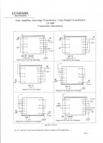
Not exactly 4 : 4.5 more like 1 : 1 but at least don't reduce the signal. Left pic signal generator direct, center pic LL1660 output, right pic pin measurement.
Attachments
![WP_20161206_010[1].jpg](/community/data/attachments/542/542094-542df3dae50c6b640dc3f5c75915bae4.jpg?hash=VC3z2uUMa2)
![WP_20161206_009[1].jpg](/community/data/attachments/542/542084-1a8392c6b37eeca2ea32d489b032c6d4.jpg?hash=GoOSxrN-7K)
![WP_20161206_008[1].jpg](/community/data/attachments/542/542065-057d82a5bc30b34b79541706a4de6d87.jpg?hash=BX2Cpbwws0)
![WP_20161206_012[1].jpg](/community/data/attachments/542/542110-6db47a19f6ff4fb05c077717ce05178b.jpg?hash=bbR6Gfb_T7)
![WP_20161206_013[1].jpg](/community/data/attachments/542/542124-a3f9c94284eb9c0b0d6f452f9b386e64.jpg?hash=o_nJQoTrnA)
Left signal generator, right LL1660 output🙂
Thank you very much Pieter!!!!
Measurements done with B+ connected and without 681R load resistor.
Wow now is really a great preamp, I have gain and lows. I recommend LL1660 Alt S SE to SE interstage when you need gain if you have a load of 100K or more. Very very good advice of Pieter (thanks again) to let me know the more inductance as more lows.
I have had another play with the scope, using sine waves this time, and plotted the output from 10Hz to 100kHz, 33k ohm loading. It took me ages to find my graph paper, unearthing all sorts in the loft in the process. Several issues of Speaker Builder, my old designs for calligraphy and signwriting, the crossover details for my Shackman electrostatic panels, etc, etc. 😀
Naturally I forgot to write down which trace is which, so won't post them until I've gone over them again, but they looked OK-ish, apart from some strange doubling at certain frequencies; it may be my scope or my settings.

Anyway, here are the relative levels, set at a nominal 1V output.


I will try this again with different loadings on the output (I have a 3k3 resistor at hand), and with my other pair of #26 valves.
Richard.
Naturally I forgot to write down which trace is which, so won't post them until I've gone over them again, but they looked OK-ish, apart from some strange doubling at certain frequencies; it may be my scope or my settings.
Anyway, here are the relative levels, set at a nominal 1V output.
I will try this again with different loadings on the output (I have a 3k3 resistor at hand), and with my other pair of #26 valves.
Richard.
-3dB at 10Hz and -1.9dB at 20kHz?
"Typical" inductance loaded tube.
IMHO 90H primary inductance is not too much and avoid heavy loading (low load resistor).
"Typical" inductance loaded tube.
IMHO 90H primary inductance is not too much and avoid heavy loading (low load resistor).
So 2dB down at 20kHz is OK? I already have HF loss in my room (overdamped; I will try to change the absorption behind me to diffraction. I have to convince my wife it will look OK!), so losing more HF is not ideal.
And I am not convinced the cheap Chinese sig gen is putting out a clean signal. One of these things. 2MHz DDS Function Signal Generator Frequency Counter Square Wave Sweep TTL Panel | eBay
I have a big old valve sine generator, so I think I'll fire that up and see how it looks.
And I am not convinced the cheap Chinese sig gen is putting out a clean signal. One of these things. 2MHz DDS Function Signal Generator Frequency Counter Square Wave Sweep TTL Panel | eBay
I have a big old valve sine generator, so I think I'll fire that up and see how it looks.
Last edited:
Using 15k to 600ohm transformer will give 3.5dB of gain, but what about the 15k to 150ohm? What will be the gain and output impedance?
How do you calculate that?
How do you calculate that?
So 2dB down at 20kHz is OK? I already have HF loss in my room (overdamped; I will try to change the absorption behind me to diffraction. I have to convince my wife it will look OK!), so losing more HF is not ideal.
And I am not convinced the cheap Chinese sig gen is putting out a clean signal. One of these things. 2MHz DDS Function Signal Generator Frequency Counter Square Wave Sweep TTL Panel | eBay
I have a big old valve sine generator, so I think I'll fire that up and see how it looks.
If you are using the switchmode PSU that came with the sig-gen, then you may get noise injected along with the signal. That is what I found with a similar Chinese gen and PSU. Putting a decent power supply on the gen made a huge difference.
I can try that. But the valve sig gen gave the same result.If you are using the switchmode PSU that came with the sig-gen, then you may get noise injected along with the signal. That is what I found with a similar Chinese gen and PSU. Putting a decent power supply on the gen made a huge difference.
And is the 2dB droop the price I must pay for using the transformer output? In which case maybe I should try Ale's gyrator.
Felipe el Mago, connect different relation ship between primary and secondary.
The out of 26 shows that the valve give some amplification.
BTW in this case, are you giving a solution for a non existent problem....
Best Regards
The out of 26 shows that the valve give some amplification.
BTW in this case, are you giving a solution for a non existent problem....
Best Regards
Returned to LL1660 Alt Q 4.5 : 1 without the load resistor, is enough gain for my audio system.
- Home
- Amplifiers
- Tubes / Valves
- #26 pre amp