How important are separate filament transformers for the 26 preamp?
Is there really an audible difference between these two scenarios:
1) power transformer with electrostatic screen, HT and 5V rectifier windings plus two separate individual filament transformers each dedicated to one 26 tube filament
2) one custom power transformer with electrostatic screen, HT and 5V rectifier windings, and two 6.3V windings for the 26 tube filaments.
I suppose scenario 1) offers the best performance on paper as the transformers are totally isolated, but it also involves a lot more real estate in the power supply. I'm willing to go with 1) if there is truly an audible difference.
Anyone tried both scenarios?
.
Last edited:
#1 is the best 'cause, you can use Coleman regs as intented by the designer and because you can power up filament xfrm and ht xfrm indipendently extending #26 lifespan. My 2 cents.....
Hi Andy,
all these are possible:
1:1.4
1:2.8
1:5.6
5.6:1
2.8:1
1.4:1
Thomas
I'm wondering about the SE to PP ratios, so the PP would be 1+1
These aren't usually quoted by Lundahl.
andy
#1 is the best 'cause, you can use Coleman regs as intented by the designer and because you can power up filament xfrm and ht xfrm indipendently extending #26 lifespan. My 2 cents.....
Thanks for the reply.
Using a slow warmup rectifier on the HT should take care of the second part, no? I'm planning on using a Bendix 6106 which has a 45 second warmup time (I found three of them for $11 each at AES! All gone now...).
Regarding the first part, I don't see any philosophical difference in the way the Coleman regulators would be used just because the x-former windings would be on the same transformer rather than different transformers. The only difference I can see might be in noise level transferred to the filament windings. Am I missing something?
Hi!
I would suggest separate transformers, but with HT and rectifier heater winding on the same transformer. And another one just for the 26 filaments. This avoids that any switching noise from the 26 filament PSU gets coupled to the B+.
Plus this offers the advantage as the previous poster mentions: B+ and filaments can be switched separately.
Best regards
Thomas
... Bendix 6106 ...
 😉
😉Rod C. could explain better than me why he's suggesting separate xfrms for his regs.Regarding the first part, I don't see any philosophical difference in the way the Coleman regulators would be used just because the x-former windings would be on the same transformer rather than different transformers. The only difference I can see might be in noise level transferred to the filament windings. Am I missing something?
Hi!
I would suggest separate transformers, but with HT and rectifier heater winding on the same transformer. And another one just for the 26 filaments. This avoids that any switching noise from the 26 filament PSU gets coupled to the B+.
Plus this offers the advantage as the previous poster mentions: B+ and filaments can be switched separately.
Best regards
Thomas
Hmmm...I never thought of the reverse scenario (switching noise from the filament supply getting into the B+), I was only thinking about noise from the HT/Rectifier getting into the filament supply. Makes sense as the filaments will be solid state rectified...
Thanks!
Yes, I recommend a separate transformer for each DHT filament - for exactly the reasons Thomas has described. Noise coupling, even at very small levels, is the fastest way to degrade any amplifier!
Hi Andy,
For the SE to PP, these would be possible:
5.6:1+1
2.8:1+1
4:2.8+2.8
2:2.8+2.8
1:2.8+2.8
Of course each configuration would need to be checked for performance. I found that with certain transformers different configurations perform quite differently. Also if windings are wired in parallel on the primary, inductance reduces by square law, current increases linearily. The last of the above ratios with the high step up would probably not work as well as other unless driven from very low impedance
Best regards
Thomas
I'm wondering about the SE to PP ratios, so the PP would be 1+1
These aren't usually quoted by Lundahl.
For the SE to PP, these would be possible:
5.6:1+1
2.8:1+1
4:2.8+2.8
2:2.8+2.8
1:2.8+2.8
Of course each configuration would need to be checked for performance. I found that with certain transformers different configurations perform quite differently. Also if windings are wired in parallel on the primary, inductance reduces by square law, current increases linearily. The last of the above ratios with the high step up would probably not work as well as other unless driven from very low impedance
Best regards
Thomas
Hi Andy & All,
if my initial tests for this new transformer are good, I will get a few with various different airgaps. Anybody interested to try these can borrow a pair. All you risk is the shipping cost
Thomas
if my initial tests for this new transformer are good, I will get a few with various different airgaps. Anybody interested to try these can borrow a pair. All you risk is the shipping cost
Thomas
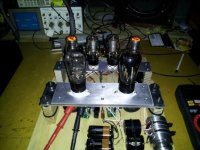
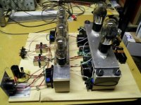
OK, the "preamp on a board" is complete (see pics). I'm using 9V battery grid bias, cascoded CCS plate loading at 6mA, gas regulator tubes for each channel fed by a cascoded CCS set to 22.5mA (0D3 +0A3 in series), LL1676 output transformers set to a 4:1 stepdown in parafeed, Rod Coleman filament regulators, and Duelund Alexander caps at input and for parafeed output. All signal path wiring is teflon jacketed 23 gauge solid core silver (DH Labs).
The power supply is from my 2C22 preamp and is a CLCLC with all film caps and Lundahl LL1638 chokes. It has two separate heater windings on the power transformer so each is set to feed one Coleman regulator with 6.8VDC. Since one winding feeds AC to the 2C22 preamp regulators I built a small rectifier/filter/regulator board on the back of the preamp to covert this to DC for the 26 preamp. Not exactly the ideal of separate transformers for HT and each filament, but it measures OK for noise.
The purpose of this experiment is to compare the 2C22 to the 26 using the same power supply, then decide if it's worth pursuing the 26 further. I have to say I'm very happy with the 2C22, but very curious about the 26 based on what I've read here. I've accumulated 15 or so 26 tubes over the last year, including balloon and ST types of various makes.
More to follow including measurements and listening tests.
P.S.: You can see the 2kHz square wave response in the background of picture #1 - looks pretty good.
.
Attachments
Last edited:
OK, the "preamp on a board" is complete (see pics). I'm using 9V battery grid bias, cascoded CCS plate loading at 6mA, gas regulator tubes for each channel fed by a cascoded CCS set to 22.5mA (0D3 +0A3 in series), LL1676 output transformers set to a 4:1 stepdown in parafeed, Rod Coleman filament regulators, and Duelund Alexander caps at input and for parafeed output. All signal path wiring is teflon jacketed 23 gauge solid core silver (DH Labs).
The power supply is from my 2C22 preamp and is a CLCLC with all film caps and Lundahl LL1638 chokes. It has two separate heater windings on the power transformer so each is set to feed one Coleman regulator with 6.8VDC. Since one winding feeds AC to the 2C22 preamp regulators I built a small rectifier/filter/regulator board on the back of the preamp to covert this to DC for the 26 preamp. Not exactly the ideal of separate transformers for HT and each filament, but it measures OK for noise.
The purpose of this experiment is to compare the 2C22 to the 26 using the same power supply, then decide if it's worth pursuing the 26 further. I have to say I'm very happy with the 2C22, but very curious about the 26 based on what I've read here. I've accumulated 15 or so 26 tubes over the last year, including balloon and ST types of various makes.
More to follow including measurements and listening tests.
P.S.: You can see the 2kHz square wave response in the background of picture #1 - looks pretty good.
.
Is your cascoded CCS with DN2540/ or IXY...
A full schematic will be nice.
Albert, the CCS uses both IXTP08N100D2 and IXTP01N100D mosfets. I'm using the compact cascode CCS (on 26 plates) and the Large Cascode CCS (for VR tubes input) from K&K audio for this project. I've also wired up CCS's using the IXYS 10M45S parts in the past, but these K&K units are inexpensive and a bit neater looking, and come complete with heat sinks.
I'll have a schematic available once I get a few minutes to draw one - it's all in my head now...
One thing is clear - you need 200H primary inductance to get flat response down to 20Hz; my two LL1676s measure at 200H and 176H (at 100Hz). The 200H one has a -3dB of ~18Hz whereas the 176H one has a -3db of ~29Hz.
By the way, in listening tests versus the 2C22 preamp it's a pretty close comparison. So far I think the balloon 26s sound better than the ST, but I haven't run through all the versions I have yet. The balloons seem to have a more fluid, smoother sound. The Cunningham CX-326s DO seem to pick up more interference from things like overhead lighting than the ST Sylvanias, though.
I have zero problems with microphonics; I can tap on the plywood base and hear nothing through the speakers, and the Khozmo stepped attenuator does not cause issues as it clicks through the steps, so the isolation scheme seems to be working just fine.
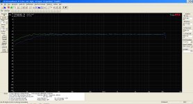
Here is a frequency response plot of both channels of my 26 preamp. You can clearly see the difference in low-end response between the 200H and 176H transformers. Overall the plot is nice and flat out past the measurement capabilities of my laptop soundcard, which verifies the good results I saw on the 2kHz square wave response with my scope.
Attachments
Hi Magz,
did you do any 10khz square wave on your scope?
Also you could do a sine wave sweep up to 100khz to see if your transformers have any ringing. My ll1660pp had some ringing around 50khz, if I remember correctly.
Putting a 4,7k 100n zobel at the output made things nicer on the scope and sounded a bit better too.
.
I have zero problems with microphonics; I can tap on the plywood base and hear nothing through the speakers, and the Khozmo stepped attenuator does not cause issues as it clicks through the steps, so the isolation scheme seems to be working just fine.[/QUOTE]
Lucky I don't have this problem either. Long to see your CCS schematic.
Putting a 4,7k 100n zobel at the output made things nicer on the scope and sounded a bit better too.[/QUOTE]
I second the above tweak.
I second the above tweak.
Hi Magz,
did you do any 10khz square wave on your scope?
Also you could do a sine wave sweep up to 100khz to see if your transformers have any ringing. My ll1660pp had some ringing around 50khz, if I remember correctly.
Putting a 4,7k 100n zobel at the output made things nicer on the scope and sounded a bit better too.
There is a little bit of ringing at the leading edge of the 2kHz square wave, but it's well-damped. 10kHz also has some. 20kHz starts to look a bit ugly at the front, but with the secondaries in parallel I expected that. Sounds smooth, though.
In my 2C22 preamp I use the LL1674 which is very similar, and I saw worse ringing on the 2kHz square wave. I added a 2nF, 520 ohm RC to the secondary and it killed that right off.
I may go back and put something on the secondaries of the LL1676, just haven't had the time to do all the tweaking yet...darn job...
These values could be tweaked a bit more. I have only done preliminary testing. Also noticed that dhtrob had an 750r at the output with different transformers though.
- Home
- Amplifiers
- Tubes / Valves
- #26 pre amp