Main difference of just VR tubes and a reg after the noise (plate side) is under a threshold -and this is a low gain line level stage after all, easy to tackle that noise aspect, not a phono- is the dynamic impedance. VR is just a stabilizer, the particular regulator has an error amplifier of 1000 times gain. A much better source, impedance-wise. You will have to evaluate after experiencing both alone, or in combination. I also find excess regulation gain stiffening tone up, but no gain too loose also. Tried for not spoiling the tone, just adding benefits. In the beta testing feedback round the first ''victim'' was a #26, second one was a C3G phones device, both transformer output. Independent feedback was heartening. Specs and subjective evaluations had been taken into account in a hopefully good mix and balance. Not easy to improve ''likes'' on the widely used SSHV1, it took some modesty, team testing, time and care. Wishing success with your experiments.
Im still following this with great interest; and cannot wait to hear how things work out for Magz and Burnedfingers.
Right now Im faithfully replicating Kevin's PSU schema...And we'll see how I like it. If I decide to do something different, I'll still have a 300v tranny and a GZ37 to start with. Considering the high voltage, VR tubes and the Salas board will be the next logical option to get my B+ down.
Right now Im faithfully replicating Kevin's PSU schema...And we'll see how I like it. If I decide to do something different, I'll still have a 300v tranny and a GZ37 to start with. Considering the high voltage, VR tubes and the Salas board will be the next logical option to get my B+ down.
If you go with choke input you will be around 240V. Then SSHV2 with heavy heat sinking will be enough.
Any chance to see a schem one day or another? 😉...second one was a C3G phones device ... transformer output.
If you go with choke input you will be around 240V. Then SSHV2 with heavy heat sinking will be enough.
Thanks. I'll have to study the documentation to see how much Vdrop it can do.
Thanks. I'll have to study the documentation to see how much Vdrop it can do.
If you do a LCRC filter you can get a few more volts drop and a little bit better pre filtering. A 1k 5W resistor will drop 40 volts at 40mA.
Gents,
Quick grounding methodology check....
On my turret board (See post 1557) I have a ground connection on the board which I will use as my central ground connection. Im assuming that:
1 - The filaments will be grounded here (through a 1 ohm 2w resistor) only (the CT on the heater transformer will float)
2 - This will be the only ground connection to the signal chassis
3 - This is where I will connect a single wire to the umbilical cord ground
If the above is correct - excellent. If not, please let me know where I've strayed.
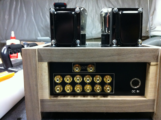
Additionally, the ground for the input/output....I assume that the input grounds will join the output ground, which only gets connected to the output transformer ? Or do these then join the central grounding point as well ?
In the power supply, I am going to ground the center tap of the HV transformer at the first cap, and have the entire PSU drain back to the plug. I will also connect the umbilical ground at this point (plug). The safety ground will connect to the PSU chassis at one point at the plug (3rd prong).
Thanks,
Steve
Quick grounding methodology check....
On my turret board (See post 1557) I have a ground connection on the board which I will use as my central ground connection. Im assuming that:
1 - The filaments will be grounded here (through a 1 ohm 2w resistor) only (the CT on the heater transformer will float)
2 - This will be the only ground connection to the signal chassis
3 - This is where I will connect a single wire to the umbilical cord ground
If the above is correct - excellent. If not, please let me know where I've strayed.
Additionally, the ground for the input/output....I assume that the input grounds will join the output ground, which only gets connected to the output transformer ? Or do these then join the central grounding point as well ?
In the power supply, I am going to ground the center tap of the HV transformer at the first cap, and have the entire PSU drain back to the plug. I will also connect the umbilical ground at this point (plug). The safety ground will connect to the PSU chassis at one point at the plug (3rd prong).
Thanks,
Steve
Last edited:
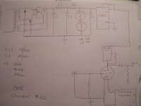
My B+ supply ONE CHANNEL
Similar to my plan, but I'm thinking I'll use a cascode CCS in place of R1 (set to 26mA), no SSHV reg and a parafeed type output with a Lundahl LL1676 amorphous cobalt core x-former wired 2:1 and a 1uF cap from the x-former back to the cathode, to get an output impedance of ~1875ohms.
That's the plan today, anyway...
More grounding thoughts....
I've started to layout my umbilical. It is a standard 8-pin screw-in molex affair. My thoughts are:
Pin 1 - Left Fil +
Pin 2 - Left Fil -
Pin 3 - Right Fil +
Pin 4 - Right Fil -
Pin 5 - B+
Pin 6 - Bias
Pin 7 - Ground
Pin 8 - Ground
Now after reading this forum and searching elsewhere, it seems that I maybe best served to ground the input jacks, output jacks, and volume control at a single point, and carry this back to the main ground in the PSU..So that could be Pin 7.
Pin 8 would ground the last bias filter, and the cathode resistors, and take that back to the PSU.
Does that make sense, or am I best served grounding everything at one central point, then use a single ground back to the PSU ?
Thanks !
I'm thinking about an XLR for the filament feed and a Speakon NL4FC for my high voltage. I'm going to float the RCA ground from the chassis both input and output and run the ground either back on the unused #1 terminal of the XLR or an unused terminal on the Speakon connector. I have had good luck taking the ground (signal) and putting a resistor 10-40 ohm in series and then running it to the star ground.
Last edited:
Well....I got one of the chassis done last night....Kinda 😉
Its all glued up and sanded; however I don't think Im going to apply the finish yet. I'll build the amplifier, test it - then if all goes well I'll be able to just remove the top and side plates and apply the finish (too clumsy on my workbench...hot soldering irons do a number on natural shellac...).
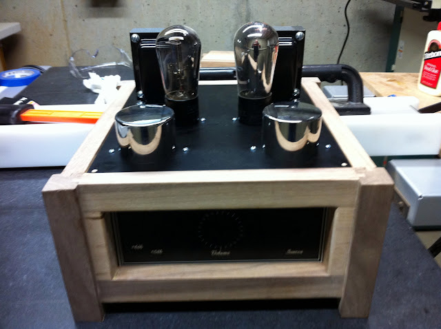

Sorry for the poor photo quality....I'll get better ones once the finish is applied.
Its all glued up and sanded; however I don't think Im going to apply the finish yet. I'll build the amplifier, test it - then if all goes well I'll be able to just remove the top and side plates and apply the finish (too clumsy on my workbench...hot soldering irons do a number on natural shellac...).
Sorry for the poor photo quality....I'll get better ones once the finish is applied.
Well....I got one of the chassis done last night....Kinda 😉
Its all glued up and sanded; however I don't think Im going to apply the finish yet. I'll build the amplifier, test it - then if all goes well I'll be able to just remove the top and side plates and apply the finish (too clumsy on my workbench...hot soldering irons do a number on natural shellac...).
Nice! What TVCs are you using, and how many steps does it have? I have a Khozmo 48-step ladder attenuator for my build, but am contemplating TVC because of the step-up ability.
.
Last edited:
Hi Steven,
I do it exactly as you have planned. Ground all signal grounds in the preamp to one point. carry all grounds of separate supplies like B+ and bias separately from PSU to preamp and connect them to your cetntal ground or ground buss there.
Nice build BTW!
Thomas
Does that make sense....
I do it exactly as you have planned. Ground all signal grounds in the preamp to one point. carry all grounds of separate supplies like B+ and bias separately from PSU to preamp and connect them to your cetntal ground or ground buss there.
Nice build BTW!
Thomas
Thanks !
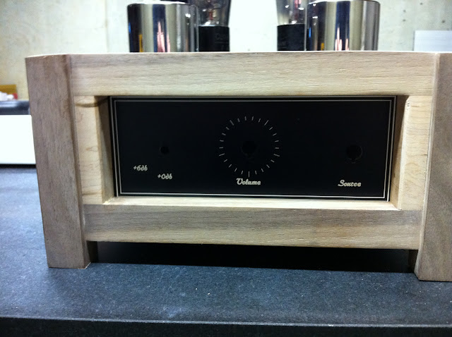
I picked up the SILK autoformers:
Silk Audio 23 Step Supermalloy TVC (Pair) | Diy HiFi Supply
They are 23 step. As you can see in my one photo, I am going to wire up that step-up ability to a switch in the front for some lower powered sources.

I picked up the SILK autoformers:
Silk Audio 23 Step Supermalloy TVC (Pair) | Diy HiFi Supply
They are 23 step. As you can see in my one photo, I am going to wire up that step-up ability to a switch in the front for some lower powered sources.
- Home
- Amplifiers
- Tubes / Valves
- #26 pre amp