Thanks Tom. I'll see if the existing 10 seconds into a resistive load will suffice in my application.
It's the HT into a pair of DHTs with a shared cathode resistor. If the HT comes up too quickly one of them hogs all the current and red plates.
It's the HT into a pair of DHTs with a shared cathode resistor. If the HT comes up too quickly one of them hogs all the current and red plates.
@Tom -- Ixys introduced some isolated high voltage analog switches which will allow resistances from the SET pin to be switched. They are 3.3V devices which is "au courant" but will require a level shift to work with the Arduino (or an Arduino hack).
High Voltage Isolated Analog Switches
DK has them in stock.
High Voltage Isolated Analog Switches
DK has them in stock.
Very neat. Some will grumble about the 600 V max.
In theory, however, a MOSFET could probably do the job. It would not provide galvanic isolation, though. With some tricks an optocoupler could probably be used as well. Hmmm... Stuff to ponder.
Is the Arduino 5 V output? Most uCs these days seem to run on 3.3 or even 1.8 V (with 3.3 V I/O).
Tom
In theory, however, a MOSFET could probably do the job. It would not provide galvanic isolation, though. With some tricks an optocoupler could probably be used as well. Hmmm... Stuff to ponder.
Is the Arduino 5 V output? Most uCs these days seem to run on 3.3 or even 1.8 V (with 3.3 V I/O).
Tom
The Arduino's I have are all 5V, as are most of my Microchip and Atmel chips. I think you can use a CD4050 @3.3V as a hex buffer, or mod the voltage regulator on the Arduino.
You could use a multiplicity of isolated optical gate drivers (Vishay VO1263) to gate a bunch of HV mosfets as well.
You could use a multiplicity of isolated optical gate drivers (Vishay VO1263) to gate a bunch of HV mosfets as well.
I think there's a 74xx244 or 74xx245 bidirectional buffer that'll do level translation as well. Either way. Any circuit that I design with a logic input will be 3.3-5.0 V compatible so no worries there.
One thought would be to just short Vgs on Q1. You'd still have a trickle current though D2, though. You could short the output to ground, but you then definitely want to get the timing between the Vgs and the output short correct or your power-down signal becomes a self-destruct signal.
Tom
One thought would be to just short Vgs on Q1. You'd still have a trickle current though D2, though. You could short the output to ground, but you then definitely want to get the timing between the Vgs and the output short correct or your power-down signal becomes a self-destruct signal.
Tom
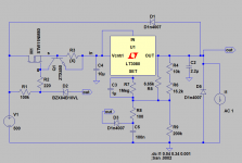
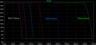
Careful with R3. If you go too low, the regulator will explode on startup if you have any capacitive load (which you do).
Tom
Tom
Hey Tom:
In reality, there is another resistor in series with R3 -- (I believe you used 22 Ohms). Rsense of 3.3 Ohms works for me.
This is on a Version 1.0 board. I have Version 2.1 from a few years back yet unpopulated. Will get this one working as well.
In reality, there is another resistor in series with R3 -- (I believe you used 22 Ohms). Rsense of 3.3 Ohms works for me.
This is on a Version 1.0 board. I have Version 2.1 from a few years back yet unpopulated. Will get this one working as well.
I just purchased a 21st Century Maida Regulator and wanted to make sure I was selecting parts correctly.
I'm using it to supply the -300V necessary for this project: Valve DAC from Linear Audio volume 13
According to the table, for 300V output, 200mA avg and 400mA peak, closest resistor values are 10 ohm for R3 and 150k ohm for R9. The suggested transformer is one with a 275V secondary.
Does this seem correct? Also, potentially a dumb question, but does the transformer output need to be rectified DC before connecting to the Maida Regulator?
Yep. Those values are correct.
The reason the transformer voltage seems high is that I account for mains variation in the spreadsheet.
You do need a rectifier and smoothing cap between the transformer and the Maida Reg.
Tom
The reason the transformer voltage seems high is that I account for mains variation in the spreadsheet.
You do need a rectifier and smoothing cap between the transformer and the Maida Reg.
Tom
I just purchased a 21st Century Maida Regulator and wanted to make sure I was selecting parts correctly.
I'm using it to supply the -300V necessary for this project: Valve DAC from Linear Audio volume 13
According to the table, for 300V output, 200mA avg and 400mA peak, closest resistor values are 10 ohm for R3 and 150k ohm for R9. The suggested transformer is one with a 275V secondary.
Does this seem correct? Also, potentially a dumb question, but does the transformer output need to be rectified DC before connecting to the Maida Regulator?
The transformer output does indeed need to be rectified. You'll need a filter capacitor too. The rectifier could be a bridge or 2 diodes depending on whether the transformer is centre-tapped or not.
150k for 300V is in accordance with the formula in the design documentation.
As for the transformer, a 275V secondary seems suitable (multiply by √2 to get a rough estimate or rectified output voltage) but there are lots of things to consider here.
- The rectified DC has a 100Hz/120Hz (depending on where you are) ripple superimposed in it. The amplitude of the ripple is dependent on the size of your filter capacitor and the current draw.
- The regulator needs at least 15V across it to regulate correctly. So you need at least 315V rectified DC into the regulator at your 400mA peak current requirement.
- That 315V is measured at the low point of the ripple. Your mains voltage varies throughout the day so it also needs to be measured at your lowest mains voltage.
- The transformer secondary has a resistance so there's a current-dependent voltage drop there too which will reduced the rectified voltage you see.
Thanks for the responses! Starting to feel like I should have just used my project's integrated power supply lol.
Do you have any suggestions for a rectifier and proper smoothing cap? Is there a PCB or something available that I can put between the transformer and the Maida Regulator?
Do you have any suggestions for a rectifier and proper smoothing cap? Is there a PCB or something available that I can put between the transformer and the Maida Regulator?
Something like a KBPC2510 would be easy to mount in the chassis. Then just solder the cap directly to the rectifier.
Tom
Tom
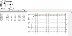
I tried that PSUD software and came up with this arrangement. The average current load of the DAC I'm making shouldn't be more than 100 mA. I was using the 400 mA peak before because it's the default suggestion in the spreadsheet.
Going to order a custom 300 V, ~70 VA toroidal transformer from Toroidy.
Going to order a custom 300 V, ~70 VA toroidal transformer from Toroidy.
Attachments
Hi Sonny. I'm already using a Maida regulator in that context and I'm happy to share the part values I used. If you're using the Neurochrome Maida PCB then yes, you will need upstream rectification/filtering.
I think I got the parts figured out other than the heatsink. I can't find any that have a thermal resistance of less than the 1.56 K/W suggested by the spreadsheet.
For a 400 mA peak, 200 mA average output at 300 V, what kind of heatsink is recommended for the STW11NK90Z?
For a 400 mA peak, 200 mA average output at 300 V, what kind of heatsink is recommended for the STW11NK90Z?
+1 for PSUD-II. Make sure to run at low mains, so set the simulation up so that you use 90% of the specified transformer voltage. That'll ensure that the circuit works if the mains are 10% low. Ensure that the valleys of the ripple voltage are at least 15 V above the desired output voltage under those conditions.
The reason 200 mA, 400 mA were in the spreadsheet as default values is that I used them for my DG300B which is where the Maida Regulator and spreadsheet came from. There's nothing magical about them.
Base the calculation on the current draw of your circuit. You can figure that out either from measurements or by drawing the load lines for the various tubes you use at the operating points you're running and calculating it.
You will find that the thermal resistance suggested for the heat sink increases as the load current decreases. Dissipated power = (Vout-Vin)*Iout.
A 3" long chunk of the 2.000" serrated fin profile from HeatsinkUSA would be my choice. That'll get you to 1.5 K/W.
Tom
Last edited:
Thank you, I'll order a 3-inch segment of that. The average current output will likely never exceed 100 mA, so I think the heatsink will be more than enough.
- Home
- Vendor's Bazaar
- 21st Century Maida Regulator