The 21st Century Maida Regulator can handle a wide variety of MOSFETs for the cascode device. I don't foresee any issues using the FDL100N50F as long as the unregulated B+ doesn't exceed the 500 V rating of the FDL... on startup.
Tom
Tom
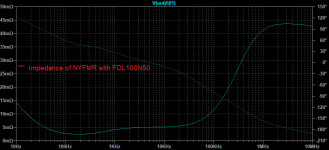
Is there a good way to predict whether instability would result from the FDL100N50F or any other MOSFET that has a greater SOA?
If you plot the output impedance wrt frequency you can estimate phase margin by looking at the Q of the impedance peak (if there is one). It looks to be stable.
You can make the NYFMR unstable by playing with the values of the output capacitor, its ESR, or the other caps.
Attachments
Maida with smps
Hello, thank you Tom for posting your circuit on this public forum. I've learned a lot! I will probably pick one up on the Neurochrome site, but have a few questions:
Hello, thank you Tom for posting your circuit on this public forum. I've learned a lot! I will probably pick one up on the Neurochrome site, but have a few questions:
- I have a high voltage switching supply I was thinking of using for an amp. Can this Maida regulator work with a smps?
- Does this regulator reduce ripple at higher frequencies (200kHz) as well?
- What is the bandwith of the ripple attenuation and regulation?
[*]I have a high voltage switching supply I was thinking of using for an amp. Can this Maida regulator work with a smps?
Absolutely.
[*]Does this regulator reduce ripple at higher frequencies (200kHz) as well?
Yes.
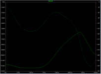
[*]What is the bandwith of the ripple attenuation and regulation?
You can see the simulated line rejection in attached figure. You should see about 70 dB of attenuation at 200 kHz.
Tom
Attachments
I was playing around for fun with Ltspice to see if I could drop the PSRR even further (though I image there would be no practical benefit). I was able to get extremely high PSRR by adding a Mosfet pre-filter. Not bad for $10 of extra parts.
Attachments
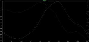
Don't be too fooled by very high PSRR -- when you get very low simulations, the real world of dust and other contaminants reduce the impedance!
For output ripple AND output impedance reduction, you might be interested in the sub-thread that starts with post 150.
For output ripple AND output impedance reduction, you might be interested in the sub-thread that starts with post 150.
Thanks CPaul, I did read those posts a while back and am currently using the "Go for Broke" version with an LT3081. Doing some sims of a MOSFET pre-reg was a just for fun trial to see how much simulated PSRR I could get. Likely won't actually implement it in practice.
Hi Tom, Thank you for your schematic and measurements.
20µV seems unreal ! I will definitely try it !
Will it hold the same/close performance on eyelets construction ?
I know I should keep 15V over the output.
If I use on 230V mains (It can vary a lot 210/240) it will probably loose regulation ? In this case should I stick with CLC or am I worrying too much ?
Also CPaul would you suggest me to use your the mod values over the V1 schem ?
Thank you
Will it hold the same/close performance on eyelets construction ?
I doubt it. You're welcome to buy one of my boards, though: 21st Century Maida Regulator: A modern B+ voltage regulator – Neurochrome
Tom
Hi Frederico, I assume you're referring to the the changes in R and C components I posted in this thread. (If not, what post number?) Simulations demonstrate and I don't doubt that these modifications will lead to improvements in output impedance and power supply regulation over the stock design. I believe that Tom agrees that this is the case, although of course, he should speak for himself on the matter.
My biggest concern is that this mod has not gone through the rigorous testing that Tom subjected his design to. Although I don't see why it would happen, there is always the possibility that the necessary protection in real world use (power up, down, momentary output short) would be absent.
Since I posted the mods, I've had some further thoughts on changes to Tom's excellent and apparently quite durable design. Remember the audio electronics enthusiasts' motto: "If it works well, modify it!"
Regulators such as the LT3080 and LM317 employ a ground-referenced voltage divider whose output is connected to the adjust pin and whose input is driven by the regulator output. This is actually a form of positive feedback, the type which degrades regulator performance! The modification I propopsed reduces the amount of feedback applied over the lower frequency portion of the audio band. It improves little in the sub-sonic portion and nothing at DC.
To address this, you might consider a zener bypassed by a large capacitor between ground and the LT3080 SET pin to allow for a slow startup and deal with Zener noise. But a mighty cap would be needed for low audio frequency noise. And the impedance of high voltage zeners at reasonably small bias currents is fairly high, still enabling a lot of positive feedback at DC. I took a different approach in the regulator I'm using in my basement lab. It's based on "The Denali Voltage Reference" appearing in the October 2017 edition of audioXpress.

I've had this running for some time now. Built on a breadboard and not intended for sale, I had no desire to run it though Tom's extensive testing, and have only used it for loads of a few ten's of milliamps. But I can think of no reason that it wouldn't work for the higher currents that Tom's design accommodates.
If you decide to build it, I would recommend using the components between the inputs and outputs that Tom used to benefit from his safety testing. I used V1 (which draws no current in normal use) to avoid the small amount of unregulated line noise that passes through Tom's 100k / zener diode voltage divider and would otherwise appear on the gate of my M2.
R1, R3-R5 and R11 form the voltage divider that sets the reference voltage at the junction of R9 and the anodes of D1 and D3: 1.25V x (1 + {R4 + R5 + R3 + R1} / R11 ) Even though we see the same DC positive feedback phenomenon we are trying to avoid in Tom's design, the DC impedance at the D1 anode is less than 100 ohms! (Positive feedback due to the above resistive divider multiplies the LMV431's DC resistance of .25 ohms by a factor of 400 at most for less than 500V out.) This means the amount of DC feedback is less than 100 / 1k (R9) or about .1 instead of the almost 1 in the original design. This reduces the change in output voltage when your neighbor's industrial-strength air conditioner compressor turns on and lowers the neighborhood's AC line voltage. The C5 / R11 divider keeps the impedance and noise due to U1's reference across the entire audio band well below (about 1 ohm and about 300nV per root Hertz) that of a Zener with a much smaller and cheaper capacitor and allows for a slow startup. D1, D3 and D7 provide protection during discharge. Alas, I have no PCB design for this.
Anyway, please excuse my digression. It was just a nice opportunity to refer to my little Denali in case you might find it useful.
My biggest concern is that this mod has not gone through the rigorous testing that Tom subjected his design to. Although I don't see why it would happen, there is always the possibility that the necessary protection in real world use (power up, down, momentary output short) would be absent.
Since I posted the mods, I've had some further thoughts on changes to Tom's excellent and apparently quite durable design. Remember the audio electronics enthusiasts' motto: "If it works well, modify it!"
Regulators such as the LT3080 and LM317 employ a ground-referenced voltage divider whose output is connected to the adjust pin and whose input is driven by the regulator output. This is actually a form of positive feedback, the type which degrades regulator performance! The modification I propopsed reduces the amount of feedback applied over the lower frequency portion of the audio band. It improves little in the sub-sonic portion and nothing at DC.
To address this, you might consider a zener bypassed by a large capacitor between ground and the LT3080 SET pin to allow for a slow startup and deal with Zener noise. But a mighty cap would be needed for low audio frequency noise. And the impedance of high voltage zeners at reasonably small bias currents is fairly high, still enabling a lot of positive feedback at DC. I took a different approach in the regulator I'm using in my basement lab. It's based on "The Denali Voltage Reference" appearing in the October 2017 edition of audioXpress.
If you decide to build it, I would recommend using the components between the inputs and outputs that Tom used to benefit from his safety testing. I used V1 (which draws no current in normal use) to avoid the small amount of unregulated line noise that passes through Tom's 100k / zener diode voltage divider and would otherwise appear on the gate of my M2.
R1, R3-R5 and R11 form the voltage divider that sets the reference voltage at the junction of R9 and the anodes of D1 and D3: 1.25V x (1 + {R4 + R5 + R3 + R1} / R11 ) Even though we see the same DC positive feedback phenomenon we are trying to avoid in Tom's design, the DC impedance at the D1 anode is less than 100 ohms! (Positive feedback due to the above resistive divider multiplies the LMV431's DC resistance of .25 ohms by a factor of 400 at most for less than 500V out.) This means the amount of DC feedback is less than 100 / 1k (R9) or about .1 instead of the almost 1 in the original design. This reduces the change in output voltage when your neighbor's industrial-strength air conditioner compressor turns on and lowers the neighborhood's AC line voltage. The C5 / R11 divider keeps the impedance and noise due to U1's reference across the entire audio band well below (about 1 ohm and about 300nV per root Hertz) that of a Zener with a much smaller and cheaper capacitor and allows for a slow startup. D1, D3 and D7 provide protection during discharge. Alas, I have no PCB design for this.
Anyway, please excuse my digression. It was just a nice opportunity to refer to my little Denali in case you might find it useful.
Regulators such as the LT3080 and LM317 employ a ground-referenced voltage divider whose output is connected to the adjust pin and whose input is driven by the regulator output.
The VRef of the LM317 is more correctly stated being "referred" to the output pin, providing a fairly constant ~ 1.25V between OUT and ADJ.
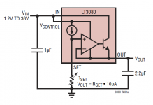
The LT3080/LT3081 uses a current source into Rset to fix the reference voltage at the non-inverting input. It is ground-referenced.
Agree.
My point was that both use divider networks to apply positive feedback from their output to their input terminals.
My point was that both use divider networks to apply positive feedback from their output to their input terminals.
Agree.
My point was that both use divider networks to apply positive feedback from their output to their input terminals.
Huh?
Attachments
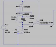
You need to look at the schematic that I posted to understand how the LT3080 and the LM317 are used in high voltage regulators by Tom, me and others - with the referenced positive feedback network.
You are correct that the LT3080 sources a very accurate 10uA current meant to flow through a resistor to establish a voltage, and of course, it does this very well - that's the genius of the part.
We are generally reluctant to employ an R = 40MegOhm resistor to establish 400V out, although I have tried a 30MegOhm resistor, and it does give me 300V! You can even parallel it with a capacitor C to obtain a turn on time constant of R x C.
Maybe someone should overcome this reluctance, build it that way, and run it for a while to see if there are any surprises over time and use!
30 MΩ is awfully high. I get nervous with impedances much over 1 MΩ. At those levels, any flux residue, dust, humidity, whatnot will impact the DC precision of the circuit.
I use the 10 uA to set a reference voltage across a resistor. This sets up a reference current of 2 mA in the resistor that sets the output voltage. That's how I can have a 200 kΩ resistor set the output voltage to 400 V.
Tom
I use the 10 uA to set a reference voltage across a resistor. This sets up a reference current of 2 mA in the resistor that sets the output voltage. That's how I can have a 200 kΩ resistor set the output voltage to 400 V.
Tom
I'm with you on your caution, Tom. I soldered the connections to the 30Meg SET resistor off the surface of my breadboard. I even drilled holes through the board so that none of the relevant leads touched it.
All that being said, Digikey lists 263 1% surface mount resistors between the values of 10 and 50MegOhms IN STOCK! ( https://www.digikey.com/products/en/resistors/chip-resistor-surface-mount/52 ) Some folks must have figured out how to get around such concerns. And apparently, worries like this are for sissies such as you and I. 🙂 It seems that Real Men have uses for the 10 and 500GigaOhm, yes, let me repeat that, 500GigaOhm resistors that Digikey also has in stock!
Thoughts?
I'm planning to use the LT3081 myself as it has very slightly better noise specs, bigger SOA, and a 50uA set current which should decrease problems associated with leakage. Negative is that it doesn't come in the same package format, so I'll see what performance I can get using a TO-220 (LCSC.com has them for cheap in quantity).
- Home
- Vendor's Bazaar
- 21st Century Maida Regulator