It should be very good.
My version of CFA using OITPC, although it used very cheap components, but it reproduce the best attack time of music instruments of all amplifiers that I ever heard.
Bimo, it looks that you are, except me of course, only one using OITPC in your design.
I asked Cordell to comment on it, he promised he will, but he forgot about it.
Bimo, it looks that you are, except me of course, only one using OITPC in your design.
I asked Cordell to comment on it, he promised he will, but he forgot about it.
Sometime we afraid to try a new things or our ego is too high to try other people ideas.
Sometime we afraid to try a new things or our ego is too high to try other people ideas.

Very nice indeed, dadod! 😉
Yes, your skills and originality are present as well.
I progressed in the drawing of the mechanical part of the CFA 100W version (using Schaeffer tool) and I'm excited too... 😀🙂
Yes, your skills and originality are present as well.
I progressed in the drawing of the mechanical part of the CFA 100W version (using Schaeffer tool) and I'm excited too... 😀🙂
Very nice indeed, dadod! 😉
Yes, your skills and originality are present as well.
I progressed in the drawing of the mechanical part of the CFA 100W version (using Schaeffer tool) and I'm excited too... 😀🙂
I am waiting to see the result and listening impression.
I started with the design of the case that requires a lot of time to get the desired result  .
.
Then I'll finish with the building of the cards.
In short, in reverse of the usual process, I imagine 🙄
.Then I'll finish with the building of the cards.
In short, in reverse of the usual process, I imagine 🙄
I wonder if somebody had made complete IRL measurements of this real masterpiece ?
Richard ?
I made a sim of this amp today, and cannot even believe in what I had seen.
Flat loop gain in all the audible bandwidth, Incredible low distortions, with no hf components, better than a class A. (see attached), rock stable. As far i had seen, the only little flaw is the clipping behavior. But who want to clip an hifi amp ?
May-be a good idea should be to add some diode limiter at the input to avoid this situation or a clipping indicator ?
I can propose one for this amp, if you like.
Dadod, you are definitely a master.
Attachments
My version of CFA using OITPC, although it used very cheap components, but it reproduce the best attack time of music instruments of all amplifiers that I ever heard.
Bimo, what did you mean precisely by attack time of instrument? Is it perceived or simulated? If perceived, how did you come to the conclusion?
My best for perceived attack is not a CFA, and I think I know why it is so, but I can't see relationship (or aren't sure) with being a CFA or OITPC (not that i understand this scheme).
I wonder if somebody had made complete IRL measurements of this real masterpiece ?
Richard ?
I made a sim of this amp today, and cannot even believe in what I had seen.
Flat loop gain in all the audible bandwidth, Incredible low distortions, with no hf components, better than a class A. (see attached), rock stable. As far i had seen, the only little flaw is the clipping behavior. But who want to clip an hifi amp ?
May-be a good idea should be to add some diode limiter at the input to avoid this situation or a clipping indicator ?
I can propose one for this amp, if you like.
Dadod, you are definitely a master.
Thank Tournesol,
Richard measured that amp and it is showed somewere in this thread.
I amon vacation now with no PC just tablet and can not show measurement.
I following your amp, very interesting with some new ideas for me.🙂
Bimo, what did you mean precisely by attack time of instrument? Is it perceived or simulated? If perceived, how did you come to the conclusion?
My best for perceived attack is not a CFA, and I think I know why it is so, but I can't see relationship (or aren't sure) with being a CFA or OITPC (not that i understand this scheme).
You can find all about OITPC in this forum, but as you dont show your " best of all existing amp" I will not help you to understand OITPC.
You can find all about OITPC in this forum, but as you dont show your " best of all existing amp" I will not help you to understand OITPC.
Just simulated an oitpc for the first time few minutes ago (integrated to my VFA). Very interesting result. I can then quickly hear the result within an hour. Hopefully this can solve my long time problem with class B amps 🙂
Thank Tournesol,
Richard measured that amp and it is showed somewere in this thread.
I amon vacation now with no PC just tablet and can not show measurement.
I following your amp, very interesting with some new ideas for me.🙂
I'm stuck with the input stage. Unless using severely VBE matched devices, problems to be expected. And if we degenerate the second stage of the diamond, all the sand castle collapses. :-(
Diamond inputs and caccocoded VAS are not loving each others ;-(
By the way, I use "inclusive compensation" since decades (1985), without giving-it (or knowing) any name.
Last edited:
Just a comment about this. Slew rate is interesting for the ability of the closed loop to follow fast signals. So it has to be measured (or simulated) without input and output filters that are here to avoid any input signal speed to reach this limit, producing the awfull TIM that is the nightmare of J.C. ;-)I did not change design, this Slew rate is with input filter connected, internal Slew rate is the same.
The second benefit is it makes more beautiful numbers on the paper. (smiley here again).
Just a comment about this. Slew rate is interesting for the ability of the closed loop to follow fast signals. So it has to be measured (or simulated) without input and output filters that are here to avoid any input signal speed to reach this limit, producing the awfull TIM that is the nightmare of J.C. ;-)
The second benefit is it makes more beautiful numbers on the paper. (smiley here again).
In my opinion he should do all his simulations into a complex load without input filter, output "Boucherot cell" and output inductor.
That will show how likely it is that the amplifier will oscillate.
🙄
Dadod, I tried your compensation, the cap paralleled with the VAS emitter resistance, in my case, cascoded. No way.
Amusing it oscillate at the class A->AB transition point of the signal. Like a marker.
Amusing it oscillate at the class A->AB transition point of the signal. Like a marker.
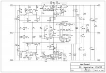
I used mosfet PSregulator in my 200CFA amp I built for me. It looked OK, playing music nicely, but one day I was intrigued by possibility that LDO regulator can easily oscillate and I checked PS regulator output with an oscilloscope and, oh horror, there was small level oscillation, about 0.2 V of very high frequency (30 to 50 MHz).
I tried different compensation but with no success. Finally I removed the drivers (when I designed it my intention was to provide enough drive for the output mosfet).
Simulation did not show any oscillation, but in real PS regulator that was solution. Now I use it in the same amp with no problem.
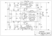
Attached PS regulator oscillating schematic and corrected one too.
It’s quite easy to correct existing regulator:
Remove Q1 , Q101, R3 , R103, C8 and C108.
Change R4 and R104 from 4k7 to 2k7 1W metal film resistors
Put the jumpers instead Q1 and Q101 between Base and Emitter positions on the board.
Thank you in advance for understanding
Damir
I tried different compensation but with no success. Finally I removed the drivers (when I designed it my intention was to provide enough drive for the output mosfet).
Simulation did not show any oscillation, but in real PS regulator that was solution. Now I use it in the same amp with no problem.
Attached PS regulator oscillating schematic and corrected one too.
It’s quite easy to correct existing regulator:
Remove Q1 , Q101, R3 , R103, C8 and C108.
Change R4 and R104 from 4k7 to 2k7 1W metal film resistors
Put the jumpers instead Q1 and Q101 between Base and Emitter positions on the board.
Thank you in advance for understanding
Damir
Attachments
I used mosfet PSregulator in my 200CFA amp I built for me. It looked OK, playing music nicely, but one day I was intrigued by possibility that LDO regulator can easily oscillate and I checked PS regulator output with an oscilloscope and, oh horror, there was small level oscillation, about 0.2 V of very high frequency (30 to 50 MHz).
Damir
Did you simulate with square wave current load?
Did you simulate with square wave current load?
I simulated with square current load, not exactly square wave and all looked OK. The oscillation was visible even without any signal/load in real amp.
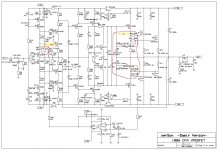
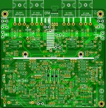
I've been asked for 100W CFA version PCB but I don't have any spare left.
If there more interest for those PCBs I can order new set of boards, so please put your PCB numbers here, as I need to order minimum 10 boards to keep the price reasonable.
There some layout improvements, and some functional improvements too, but the amp stays the same in principle.
The layout improvement is in the feedback resistors (R37), now contains two 2W in parallel and then in series with next two 2W resistors in parallel, in difference with previous version - four 2W resistor in parallel. In this case resistor voltage distortion lowers.
First functional difference is better output mosfets protection, and second is manual DC offset trim. It can work in tandem with DC servo, or individually, manual or DC servo, depends how good was the transistors matching.
list here if anyone interested:
Attachments
- Home
- Amplifiers
- Solid State
- 200W MOSFET CFA amp