Sorry... PCB is correctly.DPS is in Slovak.
I worked one and half year in Bratislava long time ago (it was Czechoslovakia then) and still remember some Slovakian.
Nothing new about PCB yet.
Thanks Richard for your effort. You have first version with the RC over VAS emitter resistor. Latest version is simulated only, not real test yet.
BR Damir
Better to use the VAS with emitter version. With diode the VAS current increases very fast with higher power supply voltages and reaches > 200 mA on +/-30V supply.
(outputstage mosfets are currently not soldered to test the vas standing current and ccs)
BR, Toni
Attachments
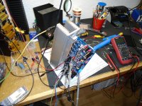
up and running ...
DC servo behaviour looks like correcting in the wrong direction?
Any hint?
BR, Toni
- used BOM V1.0.
- only 1 pair of outputstage mosfets installed
- tuned to 150ma bias
- DC offset without dc servo +13mV
- DC offset with installed dc servo opamp is -1.6V (tried LF411, NE5532 - no difference). Output on opamp goes up to ~ +13V
DC servo behaviour looks like correcting in the wrong direction?
Any hint?
BR, Toni
NE5532 is dual Opamp, LF411 is single. Their pinouts are different.
... it was a typo - of course I used NE5534 ...
NE5532 is dual Opamp, LF411 is single. Their pinouts are different.
Yes, it should be used single opamp with jfet input, LF411 is a good one. Have you inserted the opamp in correct direction, I know it's stupid question but..?
Better to use the VAS with emitter version. With diode the VAS current increases very fast with higher power supply voltages and reaches > 200 mA on +/-30V supply.
(outputstage mosfets are currently not soldered to test the vas standing current and ccs)
BR, Toni
Hi Toni,
Yes, I was testing that just now. I can see from your photo that you did not thermally connected input supper pairs as it should be (Q11, Q3 and Q12, Q4). This stabilizes the VAS current a lot but I am not sure yet if enough, so keep the version with resistors and RC combination.
BR Damir
... it was a typo - of course I used NE5534 ...
I am afraid NE5534 is not good for DC servo.
A TLO71 or LF351 will work better here than NE5534. You can try any of the OP series, like 07, 77 or OPA 9x series for the best results.
NE5534 was only for quick test to see if DC behaviour changes.
The main reason for the bad DC behaviour seems to be instability anywhere in the circuit. I can see some > 100MHz oscillation with 50mVpp on output.
I have only populated one mosfet pair. Maybe it betters with all pairs installed.
The main reason for the bad DC behaviour seems to be instability anywhere in the circuit. I can see some > 100MHz oscillation with 50mVpp on output.
I have only populated one mosfet pair. Maybe it betters with all pairs installed.
Hi Toni,
Do you have that oscillation without DC servo opamp?
What are your power supply voltages? Check +-15V on the board, does it change when you insert the opamp.
I never had any oscillation with my boards.
BR Damir
Do you have that oscillation without DC servo opamp?
What are your power supply voltages? Check +-15V on the board, does it change when you insert the opamp.
I never had any oscillation with my boards.
BR Damir
Hi Toni,
Do you have that oscillation without DC servo opamp?
What are your power supply voltages? Check +-15V on the board, does it change when you insert the opamp.
I never had any oscillation with my boards.
BR Damir
Oscillations with and without installed opamp.
Supply voltage was +/- 62V.
+/-15V are OK.
Be4 I do any other tests I will populate the board with all 8 mosfets. Such long traces without termination and the too less load capacitance due to the missing mosfets may be the reason for the oscillations. 😉
Stay tuned!
BR, Toni
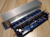
... up and running.
HF oscillations seems to be gone. DC servo is now working.
Quick THD+N test up to 37Vrms shows distortions below 100ppm through the audio band (bw 80kHz). Noise is a bit high (unweighted 1.2mV) but this may be due to the quick'n dirty test setup.
More tests coming soon.
The 2 VAS transistors 3503/1381 get relatively hot - adding a small heatsink for the next pcb revision would help a lot.
BR, Toni
Attachments
Dadod:
I am trying to get this board up and running as you know. Can you say which relationship should be between transistors are more important. You indicated the Vbe between Q11 and Q3 also between Q12 and Q4. Then the Hfe between the same ones. OR should all 4 devices have similar Vbe's and Hfe's? As soon as I get these four transistors selected I am ready to mount them on the PCB's. I am trying to understand and move forward at the same time. Thanks for ALL your help too. This is a REAL learning experience for me too.
I am trying to get this board up and running as you know. Can you say which relationship should be between transistors are more important. You indicated the Vbe between Q11 and Q3 also between Q12 and Q4. Then the Hfe between the same ones. OR should all 4 devices have similar Vbe's and Hfe's? As soon as I get these four transistors selected I am ready to mount them on the PCB's. I am trying to understand and move forward at the same time. Thanks for ALL your help too. This is a REAL learning experience for me too.
... up and running.
HF oscillations seems to be gone. DC servo is now working.
Quick THD+N test up to 37Vrms shows distortions below 100ppm through the audio band (bw 80kHz). Noise is a bit high (unweighted 1.2mV) but this may be due to the quick'n dirty test setup.
More tests coming soon.
The 2 VAS transistors 3503/1381 get relatively hot - adding a small heatsink for the next pcb revision would help a lot.
BR, Toni
Looking GOOD, Please share what they sound like when you get them on some speakers...Congratulations, I am coming right behind you SOON I hope.
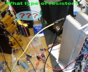
2 astx - Please reply.
8 x 50W / 1R (upper resistors)
Vendor, Type: Dale, RH50
8 x 50W / 3.9R (lower resistors)
Vendor, type: ATE, RB50
... up and running.
HF oscillations seems to be gone. DC servo is now working.
Quick THD+N test up to 37Vrms shows distortions below 100ppm through the audio band (bw 80kHz). Noise is a bit high (unweighted 1.2mV) but this may be due to the quick'n dirty test setup.
More tests coming soon.
The 2 VAS transistors 3503/1381 get relatively hot - adding a small heatsink for the next pcb revision would help a lot.
BR, Toni
Hi Toni,
I am very glad that it is working now.
From the photo I dont see RC combination connected parallel to the VAS resistor, does that mean you are using the diode there? The VAS transistors should not be hot, the VAS current can be from 5 to 6 mA (that is more then enough). If you have more then is good to lower cascode collector resistor, if VAS emitter resistor is used than use 1k2 if diode than 1k33 (if to high add a resistor inseries).
If you use VAS emitter resistor than parallel RCcombination lower THD20k.
I am out of my PC for next 5, 6 days, using tablet only.
BR Damir
- Home
- Amplifiers
- Solid State
- 200W MOSFET CFA amp