Of course virtually all high speed high resolution IC op-amps are (so-called) CFA. I think 14bit SFDR at 100MHz is done now. So next time you answer your cell phone just remember those nasty little CFA's in the base station are making it all happen.
Sorry, I was not aware there's a 250W audio power amplifier in my cell phone or in the base station, with a multiple mosfet output stage that drastically limits the ULGF at 2-5MHz or even less.
Wait... I just read the logo... it's called DIYAudio, am I wrong?
The CCS used in this amp is thermally very stable, but the current is dependent of the LED, and LED voltage drop can fluctuate a quite.
Here I suggest a novel (?) CCS, also thermally very stable but uses only bipolar transistors. It has lower dynamic resistance then ordinary feedback bjt CCS, but not much.
Damir
Actually I used already in my simulations Widlar current mirror to play CCS role, and it's almost equally thermally good as this one with Wilson current mirror, but I haven't done variable temperature simulation. I did it now for both kind and both are thermally similar, of course.
Damir
Hi Richard
At what power level is the 10kHz THD taken?
I am always surprised at the high 10-20kHz distortion of CFAs since I thought part of the point of CFA is exceedingly good high-frequency response. Doesn't that mean it should have better / lower THD at those frequencies? Doesn't seem much different than VFA.
Have fun
A little early to be jumping to conclusions. All at 10W/8 & Without heat-sink:
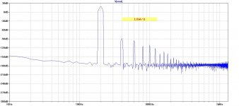
This is thd....... mostly 2H....... The 3H and higher harmonics are < -120dB.
A trim for the 2H would null even the low 2H residual out. Where to put the trim?
Got big heat sink today but might not be big enough.... looking for a fan for it.
THx-RNMarsh
Last edited:
A little early to be jumping to conclusions. All at 10W/8 & Without heat-sink:
This is thd....... mostly 2H....... The 3H and higher harmonics are < -120dB.
A trim for the 2H would null even the low 2H residual out. Where to put the trim?
Got big heat sink today but might not be big enough.... looking for a fan for it.
THx-RNMarsh
10KHz --
With the heat sink added..... same everything.... the 2H is lower now.... <-100dB as I could leave it on and OPS bias stablized at higher level.
(OPS device Temp = 50C during test).
10KHz --
With the heat sink added..... same everything.... the 2H is lower now.... <-100dB as I could leave it on and OPS bias stablized at higher level.
(OPS device Temp = 50C during test).
Hi Richard,
Could you post 10kHz FFT for 1W, 10W and 100W. Probably your heat sink is good enough for short test even 100W/8.
I am quite sure that distortion should go down with proper power supply, short twisted power supply wires and a star grounding.
Regarding 2H, it could be because I could not find between my BC transistors very good match and to compensate for that I increased one side CCS resistor from 820R to 1K.
Everyone said that 2H is not problem, specially if it's so low.
BR Damir
Last edited:
No problem with FFT..... The instrument I am using does FFT and displays the individual harmonic levels.... not a plot of them all. will display THD, THD+N and each harmonic level thru 5H. But I will shift over to A-P and do an FFT sweep, later.
That low level is OK re 2H but if there is a simple way to trim it then why not as I have the test equipment to see the null. Would a variable R for that CCS resistor do it. Something to play with, later.
BTW --- the 112W/8 THD is -- .0015-.002% at 1KHz; and .0038% at 10KHz (with 2H and 3H equal).... messy wiring and all. But best grounding.
THx-RNMarsh
Last edited:

Here are some additional numbers using 4 Ohms ---
168W at 1KHz = .0022% THD
100W at 1KHz = .0018%
100W at 5KHz = .0042%
100W at 10KHz = .0057%
Very little change with power and freq and load Z.
THx-RNMarsh
168W at 1KHz = .0022% THD
100W at 1KHz = .0018%
100W at 5KHz = .0042%
100W at 10KHz = .0057%
Very little change with power and freq and load Z.
THx-RNMarsh
Hi Guys
What is the idle current and supply voltage for these tests?
Is this Vamir's circuit above?
Have fun
What is the idle current and supply voltage for these tests?
Is this Vamir's circuit above?
Have fun
Hi Guys
What is the idle current and supply voltage for these tests?
Is this Vamir's circuit above?
Have fun
This is the amp http://www.diyaudio.com/forums/solid-state/243481-200w-mosfet-cfa-amp-77.html#post4307021.
It was design for the bias current of 140 - 150 mA per output pair and +-65 to +-70 V. I am not sure what supply voltage Richard used for that measurement.
BR Damir
Damir would the regulator you showed in post
http://www.diyaudio.com/forums/solid-state/243481-200w-mosfet-cfa-amp-59.html#post4125783
be of any help to the board we are testing?
Thanks
http://www.diyaudio.com/forums/solid-state/243481-200w-mosfet-cfa-amp-59.html#post4125783
be of any help to the board we are testing?
Thanks
This is the amp http://www.diyaudio.com/forums/solid-state/243481-200w-mosfet-cfa-amp-77.html#post4307021.
It was design for the bias current of 140 - 150 mA per output pair and +-65 to +-70 V. I am not sure what supply voltage Richard used for that measurement.
BR Damir
My supply for testing is two 60vdc .
-RNM
My supply for testing is two 60vdc .
-RNM
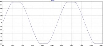
The power into 5 Ohm NI load at onset/beginning of clipping.... 0.2% THD .... was 270W. And, THD at 245W was still low .0022% THD (1KHz).
-RNM
Damir would the regulator you showed in post
http://www.diyaudio.com/forums/solid-state/243481-200w-mosfet-cfa-amp-59.html#post4125783
be of any help to the board we are testing?
Thanks
Chris, this PS Regulator is good and proven, but I would like to use one with mosfet regulating transistor instead of BJT. Go to http://www.diyaudio.com/forums/solid-state/182554-thermaltrak-tmc-amp-54.html this is what I would like to make. Obscurus made low voltage version, but I need +-65V, and yes, I think it will improve the power amp, and more importantly it has all needed protection.
Chris, this PS Regulator is good and proven, but I would like to use one with mosfet regulating transistor instead of BJT. Go to http://www.diyaudio.com/forums/solid-state/182554-thermaltrak-tmc-amp-54.html this is what I would like to make. Obscurus made low voltage version, but I need +-65V, and yes, I think it will improve the power amp, and more importantly it has all needed protection.
OK thanks, which components limit the highest voltage this will handle?
also
IF and only IF more current is needed in the output, can the output FET be paralleled to handle it?
OK thanks, which components limit the highest voltage this will handle?
also
IF and only IF more current is needed in the output, can the output FET be paralleled to handle it?
All Transistors should be for Vce higher than the input voltage except the ones used to sense DC offset at the loudspeakers.
No need to parallel the output MOSFET, just use IRFP140/9140.
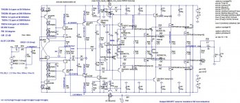
200W-CFA-VMOFET-jfetIPS
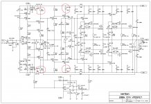
Here is a variant with complementary JFET input. No diamond nor supper pairs. The THD is higher but still quite low. IPS is bootstrap cascoded. Instead input CCS could be used simple resistor with no significant degradation. Two transistor used to isolate bootstrap from the fets current increase PSSR.
Damir
Attachments
200W-CFA-VMOSFET improvement
I improved and simplified this amp in the same time with very small changes. The VAS emitter resistor was replaced with a diode, the RC across that resistor removed, and R5 and R6 increased from 1k2 to 1k33.
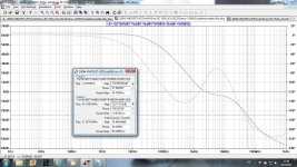
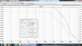
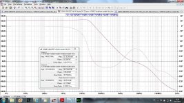
The Loop Gain is now 82 dB from zero to 20 kHz.
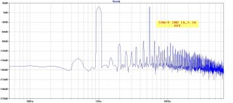
THD20 improved.
THD20k for 50W/8 dropped from 2.12 ppm to 1.5 ppm
THD20k for 200W/8 dropped from 12.7 ppm to 4.55 ppm
THD1k stayed almost the same
PM stayed the same, but GM increased from 20 dB to 40 dB
ULGF increased from 3.4 MHZ to 4.45 dB
Parallel to the output added 22 nF
Best thing is that the same PCB can be used, just some element changed and some removed.
Damir
I improved and simplified this amp in the same time with very small changes. The VAS emitter resistor was replaced with a diode, the RC across that resistor removed, and R5 and R6 increased from 1k2 to 1k33.
The Loop Gain is now 82 dB from zero to 20 kHz.
THD20 improved.
THD20k for 50W/8 dropped from 2.12 ppm to 1.5 ppm
THD20k for 200W/8 dropped from 12.7 ppm to 4.55 ppm
THD1k stayed almost the same
PM stayed the same, but GM increased from 20 dB to 40 dB
ULGF increased from 3.4 MHZ to 4.45 dB
Parallel to the output added 22 nF
Best thing is that the same PCB can be used, just some element changed and some removed.
Damir
Attachments
I'm not sure if I have the latest amp changes you just mentioned above.... but when connected to heat sinks and speakers, it is extreamly clear and detailed sounding on good speakers. Great sound stage clarity. The quality of the sound really comes thru. Now I will have to listen on even better speakers and clean up the mess of power/ground wires. The transients are sharp, quick and clean.... very nice !! I'm getting excited.

The heat sinks are still too small, though.
THx-RNMarsh
The heat sinks are still too small, though.
THx-RNMarsh
Last edited:
- Home
- Amplifiers
- Solid State
- 200W MOSFET CFA amp