Congratulations. now we know it works and works great. I am ready to buy boards and parts.
OK lets get some boards made and let everyone enjoy the singing of your amp.
Great work Damir
OK lets get some boards made and let everyone enjoy the singing of your amp.
Great work Damir
Ah, nice to see the fruits of ones labour, enjoy cheers rick
edit: instead of getting a bigger transformer, i suggest to get another same 500va transformer/rect/filter and make it mono-block type construction. we see most hi-end amps have separate transformers or secondary winding.
edit: instead of getting a bigger transformer, i suggest to get another same 500va transformer/rect/filter and make it mono-block type construction. we see most hi-end amps have separate transformers or secondary winding.
Last edited:
Nice to see it's working great ,congratulations and I'm glad to know I help a little ......🙂
Regards,Alex
Regards,Alex
Congratulations. now we know it works and works great. I am ready to buy boards and parts.
OK lets get some boards made and let everyone enjoy the singing of your amp.
Great work Damir
Thank Chris, I will prepare detailed schematic and BOM next days. I have six spare boards and if there is going to be interest I can order some more.
Damir
Ah, nice to see the fruits of ones labour, enjoy cheers rick
edit: instead of getting a bigger transformer, i suggest to get another same 500va transformer/rect/filter and make it mono-block type construction. we see most hi-end amps have separate transformers or secondary winding.
You are right about two transformers, but the problem is, one I have gives +-50 DC after the caps and for this amp to get full power I need +-65 DC.
I intended to use two PS regulators similar to one I use with my TT amp but with the VMOSFET as the regulated transistor and In this case is the same if I use one or two transformers, but one is cheaper even od double VA.
Nice to see it's working great ,congratulations and I'm glad to know I help a little ......🙂
Regards,Alex
Thank you Alex, you helped me a great deal.
Cheers, Damir
Thank Chris, I will prepare detailed schematic and BOM next days. I have six spare boards and if there is going to be interest I can order some more.
Damir
Tell me how to send the money to you..."If there is some interest?" are you kidding? 😀
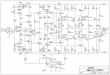
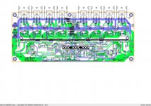
Updated schematic, PCB and BOM.
Damir
If i add more power mosfets in parallel to the output mosfets, the power will increase without effecting distortion and other specifications ?
And, how will the voltage variation of 100mV of blue LED effect the bias and the overall performance of the circuit ?
Last edited:
If i add more power mosfets in parallel to the output mosfets, the power will increase without effecting distortion and other specifications ?
And, how will the voltage variation of 100mV of blue LED effect the bias and the overall performance of the circuit ?
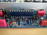
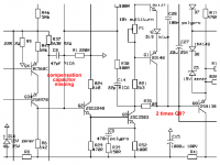
It was designed that one pair of the drivers drive two pairs of output mosfets.
I selected (matched) two blue LEDs to have the similar thermal behavior, and the LED voltage drop at 5mA was 2.75 to 2.77 V. With that LED the output bias current increased some during warm-up and than stayed stable with quite hot main heat sink.
All LEDs are blue ? Bom says 2 red 1 blue.
5mA, means you probably use 5 MM LEDs. It is relatively a too low current for BD139-140 . What is the reason to select such a high power transistor for a lowcurrent ?
So, people who wants to make this ampli have to match LEDs too ?
Sorry for many questions.
Two red LEDs and one blue LED(in the Vbe multiplier) all 3mm. Better to do some LED matching, nothing critical.
The VAS current is 6mA about, and BD139/140 are chosen because of the TO126 case, to fix them to the heat sinks.
Your question about LED was not clear to me.
Updated schematic
Hi Damir
Q6 and Q8 drawn incorrectly I think.
And is C6 in the correct place or does it need a partner?
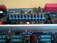
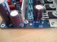
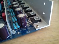
Nice to see the finished amp.
Best wishes
David
Last edited:
Hi Damir
Q6 and Q8 drawn incorrectly I think.
And is C6 in the correct place?
Nice to see the finished amp.
Best wishes
David
Thank you David, I always make such stupid mistakes. Corrected schematic added.
Best wishes
Damir
Attachments

What happen with lateral mosfet version of this amp? Will it be ready and test in close future?
What happen with lateral mosfet version of this amp? Will it be ready and test in close future?
Actually I finished one board, but got some strange occasional oscillation, even if the circuit is very similar to VMOSFET amp, even simpler, without EF VAS enhancement. Now when I finished VMOSFET one I'll go back to lateral.
Dear Damir,
congratulations to you for your new amplifier!
Count me in for 1-2 pcb's for measurements and hearing tests. 🙂
THX and BR, Toni
P.S.: found some errata on your circuit drawing. See attached picture.
P.P.S.: Would it be possible for you to add an index in your first post to easily find the latest and up2date schematics, bom and ltspice asc files? THX
Attachments
Last edited:
Dear Damir,
would it be possible to replace
would it be possible to replace
2SC2240/2SA970 with KSA992F/KSC1845F
and
2SC3503/2SA1381 with KSA1381E and KSC3503D?
BR, Toni
Dear Damir,
would it be possible to replace
2SC2240/2SA970 with KSA992F/KSC1845Fand
2SC3503/2SA1381 with KSA1381E and KSC3503D?BR, Toni
Thank you Toni for finding some of my always present errors.
I will do as you suggested, add the link in the first post to the post with correct sch bom and asc files.
Regarding replacement transistors I think that there should not be a problem specially with 3503/1381.
BR, Damir
- Home
- Amplifiers
- Solid State
- 200W MOSFET CFA amp