I think that MAYBE 4 of these operating at 120 volts input might do the trick, what do you think?
Transformateur R-CORE à fixation sur châssis 500VA - 2 x 36V - R-CORE pour châssis
Separate plus and minus and channels...it sure would look impressive if nothing else...
Yes, this is exactly where I bought it. For the mono blocks two of this Transformateur R-CORE à fixation sur châssis 500VA - 2 x 51V - R-CORE pour châssis would be a good choice.
200W CFA VMOSFET listening
Solved the DC servo problem, again layout error 😱. Now the amp DC output offset is below 1mV and singing beautifully.
BR Damir
Solved the DC servo problem, again layout error 😱. Now the amp DC output offset is below 1mV and singing beautifully.
BR Damir
...Let say we have an amp and we know its Open Loop Gain and Phase behavior, but we don't know its internal circuitry. As in most cases an amp Gain is defined with negative feedback resistors ratio (sometimes there is a cap too) and the Loop Gain reflects exactly the OLG minus the amp gain(in dB). From this is clear that it's enough to put the Tian probe in the global feedback loop only to get Gain and Phase graphs and corresponding gain and phase margins. Internal feedback loops(negative or positive - EC) are not needed to be analyzed stability wise, only if we want to have inside view, which is very useful during design phase.
Hi Damir
I didn't miss this, just been at the beach a few days and a bit slow to reply.
And the discussion in the other thread was relevant here too.
I think your ideas are reasonable for most practical amplifiers.
The outer loop is the indicator of the amp's stability.
There are theoretical possibilities for internal amp instabilities that don't show in the outer loop.
I have not yet fully worked out the theory for this but they don't seem to be a problem in practice for ordinary amps.
It is less clear for schemes with gain in different paths, like Error Correction amps.
For instance, the usual theory for Hawksford EC seems to be badly flawed.
The most common mistake I have seen is that people misunderstand exactly what "outer loop" is and where to place the probe to measure it.
People think the outer loop is just the path back to the feedback resistor but that's only a trick in the way it's usually drawn.
The true "outer loop" includes any other parallel paths, like TMC or OutputInclusiveComp, so the probe must be before they split off.
I like to check the inner loop plots as I optimize the compensation but I don't have the theory of this fully worked out either.
At the moment it's a bit trial and error, sorry I can't be more specific yet.
Best wishes
David
Hi David,
You are lucky one, we have some kind of winter here, no snow just bad weather.
In my opinion all the inner loops instability should be seen in the global (outer) loop, but yes one should know how to test that. Inner loop is stability simulation is very useful for inside look and inner loops improvements.
Best regards
Damir
In my opinion all the inner loops instability should be seen in the global (outer) loop
Unfortunately this is not true.
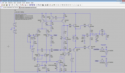
It’s fairly easy to make a two-pole compensated amp where the outer loop looks fine but the inner loop is unstable (put cascodes in the input stage and VAS/TIS, beta-enhance the VAS/TIS, connect feedback caps so both casodes are included in the loop).
This is an issue that was brought to my attention when I published my two-pole compensation paper. Some people were unimpressed that I had suggested adding cascodes and including them in the inner loop (to improved PSRR), without addressing the stability of that loop. It was true that I hadn’t thought to check this, and sure enough, although the global loop was well stable with ample gain and phase margins, the inner loop was not stable! A judiciously placed series RC to ground in the inner loop can usually solve this problem.
Presumably inner loop instability would manifest in a time-domain simulation in one way or another, but it is demonstrably false that inner loop stability can be assured by looking at a bode plot of the outer loop loop gain.
Last edited:
Unfortunately this is not true.
It’s fairly easy to make a two-pole compensated amp where the outer loop looks fine but the inner loop is unstable (put cascodes in the input stage and VAS/TIS, beta-enhance the VAS/TIS, connect feedback caps so both casodes are included in the loop).
This is an issue that was brought to my attention when I published my two-pole compensation paper. Some people were unimpressed that I had suggested adding cascodes and including them in the inner loop (to improved PSRR), without addressing the stability of that loop. It was true that I hadn’t thought to check this, and sure enough, although the global loop was well stable with ample gain and phase margins, the inner loop was not stable! A judiciously placed series RC to ground in the inner loop can usually solve this problem.
Presumably inner loop instability would manifest in a time-domain simulation in one way or another, but it is demonstrably false that inner loop stability can be assured by looking at a bode plot of the outer loop loop gain.
So, can system with good phase margin and gain margin oscillate, because instability of the inner loop?
Could you post the ASC of this with the 'judiciously place RC' clearly marked so we can see for ourselves?It’s fairly easy to make a two-pole compensated amp where the outer loop looks fine but the inner loop is unstable (put cascodes in the input stage and VAS/TIS, beta-enhance the VAS/TIS, connect feedback caps so both casodes are included in the loop).
This is an issue that was brought to my attention when I published my two-pole compensation paper. Some people were unimpressed that I had suggested adding cascodes and including them in the inner loop (to improved PSRR), without addressing the stability of that loop. It was true that I hadn’t thought to check this, and sure enough, although the global loop was well stable with ample gain and phase margins, the inner loop was not stable! A judiciously placed series RC to ground in the inner loop can usually solve this problem.
How did you see the instability? Looking at Loop Gains (Return Ratios)? Or did you use .TRANS?
Could you post the ASC of this with the 'judiciously place RC' clearly marked so we can see for ourselves?
The usual place works - at the VAS/TIS collector. You can also place it at the base of the VAS/TIS - this is not a “standard” location but I have not been able to detect (in simulation) any adverse consequences of placing it there, the benefit of this location being that it has no impact on the amplifier’s slew rate. Never had the time to test in real life.
How did you see the instability?
Bode plot of inner loop loop gain
HarryDymond said:It's fairly easy to make a two-pole compensated amp where...
I was about to ask the same as Ric so please add my request to his.
Could you post or link to exactly the ASC that shows this behaviour?
I have some suspicion that your inner loop isolation method requires modifications to the circuit and this may have mislead you.
I would be reassured to see a TRANS of the unmodified amp that confirms the instability.
Ric's question leads me to think he is on the same track.
So it would be useful if we all had precisely the same circuit to compare.
Best wishes
David
Last edited:
So, can system with ... oscillate, because instability of the inner loop?
This has been a debated in this forum for quite a while even by well educated and skilled people.
Finally, a definitive answer is close, I think.
Best wishes
David
Unfortunately this is not true.In my opinion all the inner loops instability should be seen in the global (outer) loop
Oops!
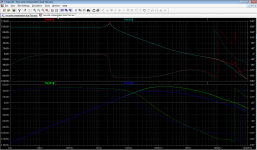
Apologies to Dadod and others - I had misremembered my simulations from before. You can indeed “see” the effects of inner loop instability in a bode plot of the outer loop loop gain - the main loop is stable, but has an unpleasant-looking peak exactly at the unstable frequency of the inner loop. See attached images showing comparison of when the inner loop is compensated vs not (A1/B1 plots = inner loop not compensated, A2/B2 plots = inner loop compensated, A plots = outer loop loop gain, B plots = inner loop loop gain).
Enjoy!
Harry.
Attachments
So, here’s a question for debate:
Given how much inner loop loop-gain gain has to be thrown away to compensate it (which presumably will result in higher distortion), is it actually necessary to compensate it, given that the effects (of inner loop instability) on outer loop loop gain are well above audible frequency range and don’t actually make the amplifier unstable?
Given how much inner loop loop-gain gain has to be thrown away to compensate it (which presumably will result in higher distortion), is it actually necessary to compensate it, given that the effects (of inner loop instability) on outer loop loop gain are well above audible frequency range and don’t actually make the amplifier unstable?
So, here’s a question for debate:
Given how much inner loop loop-gain gain has to be thrown away to compensate it (which presumably will result in higher distortion), is it actually necessary to compensate it, given that the effects (of inner loop instability) on outer loop loop gain are well above audible frequency range and don’t actually make the amplifier unstable?
Thank you Harry, that was exactly my thinking.
I looked at this somewhere in the tpc-vs-tmc-vs-pure-cherry thread.Given how much inner loop loop-gain gain has to be thrown away to compensate it (which presumably will result in higher distortion), is it actually necessary to compensate it, given that the effects (of inner loop instability) on outer loop loop gain are well above audible frequency range and don’t actually make the amplifier unstable?
As the Cherry cap is made larger, the '"main loop" becomes more stable but the "Cherry loop's" PM & GM deteriorate as the bigger cap applies more feedback around the inner loop. But the 'Cherry loop' never actually becomes unstable with bigger caps.
If you go the other way and make the Cherry cap smaller, the PM & GM of the "Cherry loop" get better but then get worse again and both 'Cherry' & 'main' loops become unstable simultaneously.
That's is with the 'main loop' always closed so shows the 'Return Ratio' of the Cherry Loop as recommended by Guru Zan rather than with the 'main loop' disabled as you show.
Haven't checked if this happens with lesser compensation schemes 😀
IMHO, this 'Return Ratio' with 'main loop' closed is the correct view.
_____________________
Harry, can you show the Closed Loop responses for your two cases please.
Last edited:
If you go the other way and make the Cherry cap smaller, the PM & GM of the "Cherry loop" get better but then get worse again and both 'Cherry' & 'main' loops become unstable simultaneously.
...
Haven't checked if this happens with lesser compensation schemes
If there is no direct transmission past the inner loop then it is mathematically inevitable that both inner and outer become unstable simultaneously.
They have exactly the same denominator in the transfer function.
So the stability is identical.
In practice the direct transmission of simple Miller comp. is very small and similarly TPC so both should behave as you describe.
This is not true for HEC.
TPC potentially has more direct transmission but I am not yet sure if it matters in practice.
IMHO, this 'Return Ratio' with 'main loop' closed is the correct view.
Can I say I have convinced you? or just that you have reached the same conclusion😉
On my side, I now realize the "unstable inner loop + stable outer" is much less a practical issue than I opined in our earlier discussions in the Cherry thread.
And I now know that the extent of direct transmission in the inner loop is the necessary condition.
Have finally done the maths for this, pretty simple once I made myself sit down and just do it.
Best wishes
David
Last edited:
So, here’s a question for debate:
Given how much inner loop loop-gain gain has to be thrown away to compensate it...
My earlier post to Ric is relevant to this, an unstable inner loop is practically always linked to instability in the outer loop so it's a moot question.
I still suspect your inner loop technique misleads you, when you add enormous capacitors to try to disable the outer loop this different load means the inner loop result is inaccurate.
Instead I think it best to use probe placement to see the "inner loop gain" - this would be in series with the Miller capacitor in your earlier example.
I think when the inner loop is compensated that the key is that the gain is not "wasted".
Miller for instance uses the "excess" gain to reduce the VAS output impedance, makes it a more "ideal" source and this partially counter effects the loss of outer loop gain.
I have tested this with Miller Input Compensation and was surprised that I could transfer gain to substantially increase the outer loop and see very little improvement in distortion.
Best wishes
David
Last edited:
I still suspect your inner loop technique misleads you, when you add enormous capacitors to try to disable the outer loop this different load means the inner loop result is inaccurate.
Did you see the screen shots posted in #711 above?
When the outer loop is simulated, this is “exact” in that nothing has been added or removed from any loop, save the Tian probe itself. This shows significant peaking at the frequency that the inner loop appears to be unstable according to the “disable outer loop” simulation method. If this inner loop simulation method were inaccurate, surely outer loop and inner loop simulations would show some discrepancy?
Thanks for the considered response, very fair points.
I wrote that I only "suspect" the technique.
It looks similar to techniques to plot outer loop gain that are now usually deprecated in favour of the Tian probe.
The broad principle seems reasonable, that it alters the impedances so potentially could alter the loop gains/return ratio.
But I don't have any analysis of when, or if, there would be a difference, so I wanted to raise my concern for discussion.
I will think a little more, any further comments appreciated.
Best wishes
David
Evil! Truly EVIL 😱In practice the direct transmission of simple Miller comp. is very small and similarly TPC so both should behave as you describe.
This is not true for HEC.
IMHO, this 'Return Ratio' with 'main loop' closed is the correct view.
This grasshopper looked at where my naive thoughts differed from Guru Zan's words of wisdoms.Can I say I have convinced you? or just that you have reached the same conclusion😉
What I found led me to grovel in shame & awe at His Guruness's feet. 🙂
______________
Harry, can you post CLOSED LOOP responses of your #711 examples?
... If this inner loop simulation method were inaccurate, surely outer loop and inner loop simulations would show some discrepancy?
Hi Harry
I have had a serious think about this, run a few simulations and I still find the enormous capacitor technique is inaccurate.
When you disable the outer loop then you have removed a factor that does influence the inner RR when the amp is in normal operation.
However, the peak in the inner loop that you show occurs at a frequency where the outer loop gain has dropped to practically zero, so there is no discernable discrepancy there.
So it may not make much difference to stability predictions for a typical circuit.
But I think the more accurate technique shows results that make it easier to understand the amplifiers behaviour.
The work I have done to clarify this issue in my own mind has certainly help me understand better.
Thank you once more.
Best wishes
David
- Home
- Amplifiers
- Solid State
- 200W MOSFET CFA amp