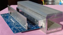
I'm not sure if I have the latest amp changes you just mentioned above.... but when connected to heat sinks and speakers, it is extreamly clear and detailed sounding on good speakers. Great sound stage clarity. The quality of the sound really comes thru. Now I will have to listen on even better speakers and clean up the mess of power/ground wires. The transients are sharp, quick and clean.... very nice !! I'm getting excited.
View attachment 487971
The heat sinks are still too small, though.
THx-RNMarsh
Thanks Richard for your effort. You have first version with the RC over VAS emitter resistor. Latest version is simulated only, not real test yet.
BR Damir
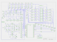
I improved and simplified this amp in the same time with very small changes. The VAS emitter resistor was replaced with a diode, the RC across that resistor removed, and R5 and R6 increased from 1k2 to 1k33.
The Loop Gain is now 82 dB from zero to 20 kHz.
THD20 improved.
THD20k for 50W/8 dropped from 2.12 ppm to 1.5 ppm
THD20k for 200W/8 dropped from 12.7 ppm to 4.55 ppm
THD1k stayed almost the same
PM stayed the same, but GM increased from 20 dB to 40 dB
ULGF increased from 3.4 MHZ to 4.45 dB
Parallel to the output added 22 nF
Best thing is that the same PCB can be used, just some element changed and some removed.
Damir
That looks very good🙂
How can you replace a VAS emitter resistor with a diode?
What resistor value do the Diode have with the current used in your schematic?
Will you make a 100W@8 ohm edition of you fine amplifier?
That looks very good🙂
How can you replace a VAS emitter resistor with a diode?
What resistor value do the Diode have with the current used in your schematic?
Will you make a 100W@8 ohm edition of you fine amplifier?
Diode dynamic resistance at the VAS bias current is very low and here diode just add 0.65V about to the VAS emitter voltage. The VAS bias current has very little influence on it.
To make 100W/8 ohm version just remove one pair of the drivers and corresponding output pairs. What is missing is a layout for it.
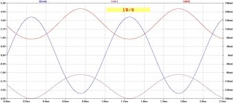
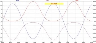
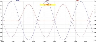
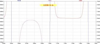
Maybe those plots can explain why this amp measure so good and sound good in the same time at all power levels. These are output HEXFET currents at different wattage, 1W, 10W and 100W on 8 ohm load, simulated of course. Last plot was expanded around zero current to show that behavior better.
Damir
Damir
Attachments
I like this amp ... please guys does anyone have a single sided pcb design for it????
I never considered to make single side pcb as this asks for to much compromises and will degrade quality of the amp.
okay if so ... i got no option .. however i can't find the printing files for the two layer pcb please can you show me where to find the pcb files ?
okay if so ... i got no option .. however i can't find the printing files for the two layer pcb please can you show me where to find the pcb files ?
From first PCB batch I've ordered I sold two pairs and the rest I used. For the moment there is no PCB offered, maybe after summer if there is going to be interest.
I'm interested in PCB's as well
I am interested in the PCB's for this AMP.🙂 You can't have to many power amplifiers😀
I am interested in the PCB's for this AMP.🙂 You can't have to many power amplifiers😀
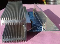

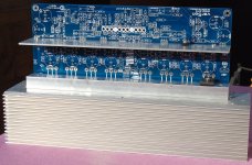
... slow progress, but progress:
Have done some metalwork to build the test sample ...
BR, Toni
Very nice Toni,
I suggest you to start to solder from the input. You can test input part separately then together with VAS and if all works correctly the rest is simple.
You can measure the voltage drop on the Q2, Q14 emitters resistors and if there to much differences (matching not perfect) it can be corrected by changing one of the input CCSs (R4 or R7) current.
BR, Damir

Thx for info.
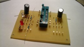
IRFP240 and IRFP9240 MOSFET "mass" matching ...
Please share your schematic for the matching, I am currently building a hfe and vbe matching tester, similar to your with the same construction techniques. Great Minds Run Together...
Attachments
Please share your schematic for the matching, I am currently building a hfe and vbe matching tester, similar to your with the same construction techniques. Great Minds Run Together...
Voila ... a bit off topic. I do not want to pollute Damir's thread. So if there is more interest maybe you open a new thread.
You need up to 3 multimeters with USB support to automatically read the measured voltages. Schematic is pretty useless without homebrew PIC software and homebrew pc software (perl script to control relay board and read and convert raw voltages from USB multimeters).
BR, Toni
Attachments
- Home
- Amplifiers
- Solid State
- 200W MOSFET CFA amp