Hans, sometimes you do strange things for unclear reasons. Maybe the amp has died now, because he was happy the way it was and needed the regulator it had? Why remove a working regulator and install a problematic step down? An oscillating problem that other people would, maybe, remove out of an audio device?
There is a saying: Do not fix it if it is not brocken. This makes some sense, don´t you think?
Do you have a schematic for the amp? If yes, someone could figure out what you did and why the amp responded like it did.
If no, no one can tell you what you did. Do you have any idea?
There is a saying: Do not fix it if it is not brocken. This makes some sense, don´t you think?
Do you have a schematic for the amp? If yes, someone could figure out what you did and why the amp responded like it did.
If no, no one can tell you what you did. Do you have any idea?
Thanks for answer
The problem was that with 48v the regulator got to hot.
I have schematics.
On similar amplifier the use step-down for vcc.
That was the reason.
With new power supply in future I will not have this problem any more...
The problem was that with 48v the regulator got to hot.
I have schematics.
On similar amplifier the use step-down for vcc.
That was the reason.
With new power supply in future I will not have this problem any more...
You can get the regulator input voltage down by simply using some resistor to turn the too high voltage into heat. A passive solution might be less complicated.
Alternative: Use a pre-regulator, so the load is shared between the two.
Alternative: Use a pre-regulator, so the load is shared between the two.
No
I have no response from the ICs
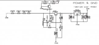
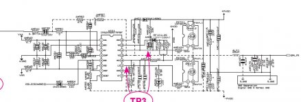
Thats the schematic and the VCC part... I think this have bruned the IC...
I have no response from the ICs
Thats the schematic and the VCC part... I think this have bruned the IC...
Attachments
Last edited:
Not to be an ***, but is it possible, that you broke some of the "platings"?? (don´t know if it´s the right word for the tiny copper tubes that go from top to bottom of the pcb connecting all layers) when you removed the old capacitors??? If it´s made as a 4-layer PCB, the damage is not repairable. I 2-layer you might be lucky to find such an error. Also one of my friends found a slight reverse leak in the diode that goes to pin 15 when his version died just out of the blue. Replacing it with a MUR120 solved it.
Last edited:
the amp does not smok or something.
So it could be no problem in PCB
That´s no guarantee..... Broken supplylines, and the crap doesn´t work anymore. Nor does it smoke/burn 🙂
Hans,
make a folder on your PC called "diyaudio_bilder".
Copy what ever you want to post here, into it.
select "Go Advanced"
Click on the small Büroklammer.
A window will open.
Click on "Datei auswählen"
Go to folder "diyaudio_bilder".
Select your picture.
Click "Upload".
Close small window, when upload done.
Click on "Submit Reply".
From time to time, erase the content of your folder, if you don´t want to waste space.
If you use any other picture hoster or what ever, any picture posted today will be lost, when they change anything or you refuse to pay for the service in the future.
So for anyone using this forum as a reference, in a while, there will be no pictures to the post and the thread useless.
As this forum is a "I help you, you help others" institution, it is not very polite to use an external host for pictures.
Last edited:
Yes that is what I do sometimes. With IMGBB in can use photo for other forums to.
back to my amp. I desolderd some IRF6645. The look to be burned. But amp still does not work. Shortcircuit on VCC and VEE. So more mosfet are burned... Desoldering is easy with my heatgun but how can I solder the new one easily?
back to my amp. I desolderd some IRF6645. The look to be burned. But amp still does not work. Shortcircuit on VCC and VEE. So more mosfet are burned... Desoldering is easy with my heatgun but how can I solder the new one easily?
What do you find at the output of the IRS IC? Pin 11+14?
As you did something unwise to the power supply, at pin´s 1+6 maybe, the IRS will be blown and the FET´s are only secondary damage. How to solder them in is your task, sorry.
I predict new FET´s will blow again, until you change IRS.
As you did something unwise to the power supply, at pin´s 1+6 maybe, the IRS will be blown and the FET´s are only secondary damage. How to solder them in is your task, sorry.
I predict new FET´s will blow again, until you change IRS.
I cant mesure anything. Power supply always shuts down....
So no results
I will looking for buying a new amp
So no results
I will looking for buying a new amp


its an IRAUDAMP5 implementation. So you have IRF6645 mosfet with better audio ability than IRFI4212H/ IRFI4019H and others.
Will change againt to WIMA MKP caps.
I will use Teufel DecoderStation 5 as preamp and decoder.
Will change againt to WIMA MKP caps.
I will use Teufel DecoderStation 5 as preamp and decoder.
It sounds like it needs its own thread....its an IRAUDAMP5 implementation. So you have IRF6645 mosfet with better audio ability than IRFI4212H/ IRFI4019H and others.
Will change againt to WIMA MKP caps.
I will use Teufel DecoderStation 5 as preamp and decoder.
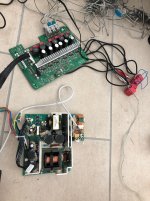
It works.
Only problem is to generate the -5V. My voltage regulators only can handle 35V. But my PSU has +-36V.
For testing I took a 5V brick and the amp works.
No load consumption is a bit hight with about 20W. It must be the active PFC.
The amp in a IRS2092 like many others. But its manufactured by Samsung in its homecinema. I saw that Sony puts IRS amps in their Shake soundsystem with the bigger IRF6775 (same as Pionneer use in his digital amp receiver) and big coils.
Now I want to find a good housing for psu and amp.
After that I want to look for a -5V regulator.
Attachments

Depending how much the chip draws on the -5v rail, you might get away with a zener divider, or a resistor in series with a 7905 to reduce the voltage it sees
- Home
- Amplifiers
- Class D
- 200W IRS2092 Amp for $20