A Linux ABEC/AKABAK client would be great, I have a 4 socket, 128GB ram compute server sitting mostly idle. Its a pretty huge step above the previously available coupled BEM FEM simulation software (non) though. Development seems quite active so perhaps the improvements to the FEM will come.
Regarding accuracy the way I would approach this is to do a sensitivity analysis on the mesh density. If increasing mesh density converges to a result and increased density beyond a certain point produces negligible change then the mesh density is high enough. I'm not formally trained though and only have one academic publication on FEM analysis so you might want to ignore me 😉
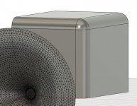
*forgot to comment on the speaker design; looks great and incorporating the cabinet round-over into the wave guide design is definitely the way forward as evidence presented on this forum has shown significant influence on directivity from round-overs.
Regarding accuracy the way I would approach this is to do a sensitivity analysis on the mesh density. If increasing mesh density converges to a result and increased density beyond a certain point produces negligible change then the mesh density is high enough. I'm not formally trained though and only have one academic publication on FEM analysis so you might want to ignore me 😉
*forgot to comment on the speaker design; looks great and incorporating the cabinet round-over into the wave guide design is definitely the way forward as evidence presented on this forum has shown significant influence on directivity from round-overs.
Last edited:
On the other hand what I was trying to look at was what effect did different woofer mounting methods have and I think the simulations answer that question reasonably well at least in a general way.
Any time the woofer is set back into the baffle it effectively looks like the woofer cone is deeper. A deeper woofer cone introduces a dip in the response so this needs to be considered carefully.
Thanks for posting the mounting methods and edge treatments. Always good to see effects relative to the options.
Was the same R18mm radius used on the cabinet edge as well? Woofer related diffraction might not be as important if you cross over low enough.
.
Last edited:
Ha Ha, I don't like to ignore anybody. In terms of the woofer there is not a great need for the amount of time and effort a formal sensitivity analysis would take. The issue with the woofer simulation mainly stems from a break down in the underlying assumptions once the frequency rises, mesh density is not the confounding factor. I plan to cross around 800Hz so the accuracy is good enough for that purpose, with an electrical LR4 at 800Hz, there isn't much to worry about 🙂I'm not formally trained though and only have one academic publication on FEM analysis so you might want to ignore me 😉
The full paper mentioned before is available from Radiation impedance of cones at high frequencies
No the cabinet edge is the same 36mm roundover that was used on the waveguide sims. The 18mm value comes from the fact the 36mm baffle would be laminated from 2 x 18mm pieces so chamfering one of them would be fairly easy.Was the same R18mm radius used on the cabinet edge as well?
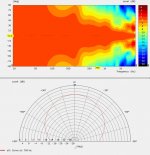
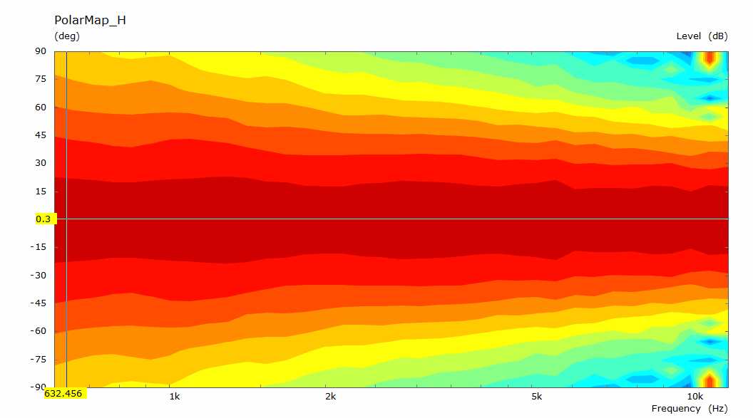
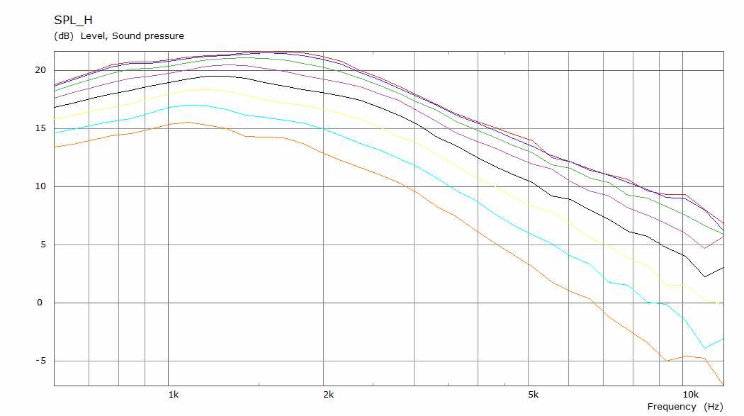
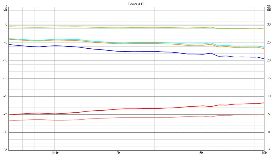
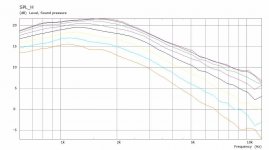
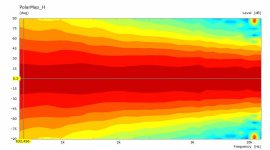
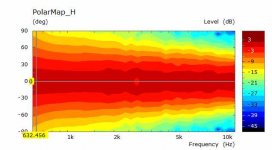
Here's a 0 deg normalized polar of the chamfered version which I think is the most practical option. 120 deg pattern at 800Hz to match the waveguide nicely.
Attachments
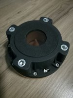
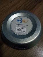
I've decided on a change in drivers from my original plan. I still have the HF146R's but I have now bought a pair of HF1440 drivers. These were always my first choice but seemed to be hard to get hold of at the time I bought the others. Anyway there was a pair in stock while I was browsing so they have now landed here 🙂
I've also had a rethink on the woofer choice. Most of the good ones seem to be easy enough to get if I order from Europe and price is hardly any different that the price for the 15PR400 locally.
I have been reading a number of different theories on how to choose a woofer based on TS parameters. All seem to make reasoned arguments but fall short of providing any objective data to base a decision on.
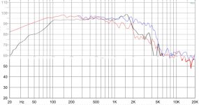
I've narrowed down to the Faital 15FH510 or 15NBX100. They are quite different in their parameters but model surprisingly similarly. The Faital is low Rms High Qms with less Le and a shallower slower rolloff towards high frequencies.
The 15NBX100 has a shorting ring and is flatter through the main pass band but peaks before a sharper rolloff.
If anyone has any real experience with these or similar drivers I would value the input before I buy.
I've also had a rethink on the woofer choice. Most of the good ones seem to be easy enough to get if I order from Europe and price is hardly any different that the price for the 15PR400 locally.
I have been reading a number of different theories on how to choose a woofer based on TS parameters. All seem to make reasoned arguments but fall short of providing any objective data to base a decision on.
I've narrowed down to the Faital 15FH510 or 15NBX100. They are quite different in their parameters but model surprisingly similarly. The Faital is low Rms High Qms with less Le and a shallower slower rolloff towards high frequencies.
The 15NBX100 has a shorting ring and is flatter through the main pass band but peaks before a sharper rolloff.
If anyone has any real experience with these or similar drivers I would value the input before I buy.
Attachments
Hi, for home use I'd choose the one that does better smaller enclosure (model either, then use same box size with the other driver and compare simulated responses). My faital 15fh520 parameters are a bit of from the factory spec and requires even bigger enclosure than with the factory TS parameters. That said I'm having now some old Beyma 15k200 drivers on that require half the box volume for similar low end extension. There is of course difference in power handling for the 15fh520 benefit but that really doesn't matter with my home setup, I'm never going to reach the limits with either driver.
The drivers sound different "naked" ( no enclosure, no crossover ), but in my three way speaker application I'm not sure if there is any real difference other than the now lower extension with the Beyma driver. One could always use EQ and power for the extension as well but it feels silly to me to do it that way. So, TS parameters might not be too important, maybe check out the box size and if there is distortion graphs available. Best thing would be to buy them both and listen side by side. Have fun!🙂
edit. either of my drivers is fine, differences are small after all and are mostly due to room interaction. Faital has a bump in response (according to simulation) which is in the boomy region of my room, beyma doesn't and thus feels better in the room. I haven't done ground plane measurements so cannot confirm 🙂
Last edited:
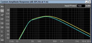
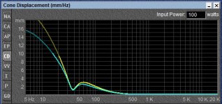
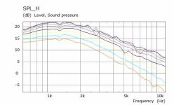
Thanks for the input. The bassbox sims above were with both drivers in a 70 litre (excluding drivers and port) enclosure tuned to 38Hz (yellow 15FH510 and blue 15NBX100). I narrowed down the choices to drivers that worked better in smaller boxes. The 15FH520 could go lower and flatter but wanted a much bigger box that I want to build.
I haven't been able to find any Klippel or distortion measurements of either, I would think that the B&C is better in that regard as it is one of their more premium models. Faital has the new 15FX600 driver which looks more similar but ends up costing the same. Of the Klippel results I have seen for B&C and Faital on other woofers, both are good but B&C do know how to make some extremely linear drivers.
I haven't been able to find any Klippel or distortion measurements of either, I would think that the B&C is better in that regard as it is one of their more premium models. Faital has the new 15FX600 driver which looks more similar but ends up costing the same. Of the Klippel results I have seen for B&C and Faital on other woofers, both are good but B&C do know how to make some extremely linear drivers.
I've also been experimenting with a different type of curve that results in a very smooth on and off axis response with a slightly rising DI approximately 3dB / decade when in an enclosure. I have tried a rectangular version of it which looks very good in an IB but the enclosure sims had some issues which I have yet to work out. I made the enclosure shallower and this had a much more pronounced effect on the directivity between 1K and 2K than I would have imagined. Part of the same issue shows up in graphs below but at 1.2 - 1.5K. There is a bit of a mesh problem where the baffle corner roundover meets the rest of the cabinet which makes the response above 5K look worse than it should. I can fix that but this sim has a pretty high element count and takes a few hours to run so I'm in no rush to prove it to myself 🙂
Attachments
Interesting, so shallower = less deep enclosure? I think this is what mabat has showed in the ATH4 thread, free standing wave guide performs better than wave guide in an enclosure. Also the mouth "roll back" works well as shallow and if I remember there was some example that filling in the roll back / making it a sphere was worse.
With big woofers it would be nice to utilize the volume backside of a wave guide for the woofer box. Also aesthetics, I prefer the classic coffin looks to free standing horns 🙂 I wonder if the enclosure would appear as shallow, regarding this phenomenon you've discovered, if the enclosure had narrower backside than the baffle (front corners would be more than 90 degrees). Curved sides are pretty popular design feature in speaker enclosures as well, might affect this phenomenon? Listening tests would be needed to check if this is an audible issue or something not to worry about. It is a lot harder to build anything else than the good old boxy box.
ps. I'm a bit jealous on your skills with the ABEC. Thanks for sharing the results and thoughts so we mortals can skip the modeling part 😀
Last edited:
15NBX100 = neo version of 15TBX100, this is B&C's cheapest 15" sub driver. It has great performance but is not as linear as their more recent (and more expensive) drivers. If you have the budget this would be my choice:
Eighteen Sound - Professional loudspeakers
Eighteen Sound - Professional loudspeakers
But how to understand the 900W AES needed ? - Say against a Faital 15PR400 rated at 400 W AES for illustration ?
thanks for sharing this kipman725,
I am also intrigued by the 15NTLW3500. if i were to build a 2-way with this,which horn and cd combo would be your suggestion?
25sqm room, will use Hypex Fusion.
I am also intrigued by the 15NTLW3500. if i were to build a 2-way with this,which horn and cd combo would be your suggestion?
25sqm room, will use Hypex Fusion.
If you have the budget this would be my choice:
Eighteen Sound - Professional loudspeakers
But how to understand the 900W AES needed ? - Say against a Faital 15PR400 rated at 400 W AES for illustration ?
Well a high AES power rating is a desirable property for a driver (so long as its not taken to the point where it harms efficiency as in car audio drivers) as it means that the speaker will be subject to less thermal compression as the motor is better able to dissipate heat. In Home audio its questionable though whether enough power would be put into the motor to cause compression as this would result in ear destroying SPL from anything apart from a subwoofer.
The thing that appeals to be for the 15NTLW3500 is the excellent kipple data I have seen for the related 18sound drivers with this type of motor:

which should result in very low distortion and the on axis frequency response that is free of resonant peaks showing good damping of cone breakup.
thanks for sharing this kipman725,
I am also intrigued by the 15NTLW3500. if i were to build a 2-way with this,which horn and cd combo would be your suggestion?
25sqm room, will use Hypex Fusion.
I it depends on what coverage angle you want? I use 90x40 at home. You can work this out by drawing a scale diagram of the room and speaker positions and plotting the desired coverage area.
You want the horn and the driver to match in horizontal directivity at the crossover frequency in these types of systems. The wider the dispersion of the horn the lower that frequency will be. Also the lower the crossover frequency the less the center to center distance of the drivers and the less vertical response anomalies at the crossover frequency.
Taking into account the typical desire for wide dispersion in a home system you will want to crossover quite low (perhaps around 600Hz) for a 15" driver and horns that work so low are quite large. Perhaps RCF HF950 and ND950 1.4 would work well or a coaxial compression driver. Lots of trade-offs between low and high frequency performance in a two way design.
Yes shallower means less deep, 300mm of box behind the baffle instead of 350mm that I used earlier. A freestanding waveguide with the right kind of rollback can produce less diffraction than a similar waveguide in a baffle. Whether it is "better" is not so easy to say because the entire enclosure has an impact on directivity and diffraction. I will post something later that shows a freestanding guide with a 50mm roundover and a cone behind.Interesting, so shallower = less deep enclosure? I think this is what mabat has showed in the ATH4 thread, free standing wave guide performs better than wave guide in an enclosure. Also the mouth "roll back" works well as shallow and if I remember there was some example that filling in the roll back / making it a sphere was worse.
I would imagine the total path length together with any changes of direction would set the effect on directivity vs frequency. I can try a curved cabinet to see the effect.With big woofers it would be nice to utilize the volume backside of a wave guide for the woofer box. Also aesthetics, I prefer the classic coffin looks to free standing horns 🙂 I wonder if the enclosure would appear as shallow, regarding this phenomenon you've discovered, if the enclosure had narrower backside than the baffle (front corners would be more than 90 degrees). Curved sides are pretty popular design feature in speaker enclosures as well, might affect this phenomenon? Listening tests would be needed to check if this is an audible issue or something not to worry about. It is a lot harder to build anything else than the good old boxy box.
I'm glad the effort is valuable to someone other than me 🙂 The learning curve with ABEC is quite vertical and without Mabat's tool and DonVK's guidance I expect I would have given up long before now.ps. I'm a bit jealous on your skills with the ABEC. Thanks for sharing the results and thoughts so we mortals can skip the modeling part 😀
Thanks for the shot of the Klippel results it certainly backs up 18 Sound's Tetracoil marketing information where they show very symmetric results. I did look at this driver for that reason, two things are against it the first one being a high Fs and the second was it not being easily available without a long wait. I'll put the figures into a box modeler to see if the high Fs is a deal breaker.15NBX100 = neo version of 15TBX100, this is B&C's cheapest 15" sub driver. It has great performance but is not as linear as their more recent (and more expensive) drivers. If you have the budget this would be my choice: 15NTLW3500
Do you have any data on the newer B&C drivers I don't see them being that much better than the 15NBX100 but they are quite a bit more expensive with even more ridiculous power ratings for home use.
There is no reasonably priced 3D Printer (that I have seen) that can produce anything like these waveguides in the kind of finish I would accept in my living room. The second benefit of the CNC is that I can produce the entire cabinet with it and use it for a lot of other woodworking tasks.Fluid yeeaa! You re going with a cnc? why not 3d printer?
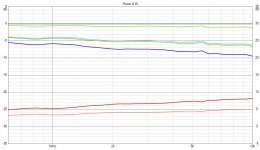
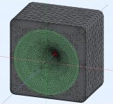
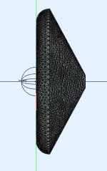
Here is a try at a Freestanding simulation using the same waveguide as before but placed into a 50mm radius rollback joined to a cone. The directivity is taken to a lower level than an Infinite baffle but not quite as low as the enclosure. The sim has some issues with numerical stability possibly from the interface / horn / rollback junction. The general idea can be seen but the random peaks and dips make it harder. Smoothing the sharp edge from the rollback to the cone would probably help too.
Attachments
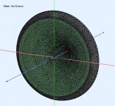
Seems to me that the glitches are just numerical issues - probably most of them, if not all. Try CircSym mode with high mesh resolution (~40 kHz), I think they will go away as they would on a real device.
- At least if the rollback is really smooth. It's hard to say from the picture.
- At least if the rollback is really smooth. It's hard to say from the picture.
Last edited:
Do you have any data on the newer B&C drivers I don't see them being that much better than the 15NBX100 but they are quite a bit more expensive with even more ridiculous power ratings for home use.
If you skip through this guys videos I think there might be some shots of the kipple data:
Bennett Prescott - YouTube
(There are also lots of general comments about the differences in the newer drivers)
From what I recall of the BL(x) curve for the 15TBX100 had a slight slope (so positive/negative excursion asymmetry) but otherwise well behaved until xmax. Also some kms(x) asymmetry but still good compared to most drivers. What would worry me a bit about using it in a two way though is the strong cone breakup ~1.7 kHz.
I would agree, I don't have a working CircSym template as yet this is the first axisymmetric curve that has interested me enough to simulate it this way.Seems to me that the glitches are just numerical issues - probably most of them, if not all. Try CircSym mode with high mesh resolution (~40 kHz), I think they will go away as they would on a real device.
- At least if the rollback is really smooth. It's hard to say from the picture.
The rollback is a 50mm fillet but the junction to the cone is not smoothed.
- Home
- Loudspeakers
- Multi-Way
- 2 way waveguide speaker build ABEC modelling