alternative IR film
If you can't find that special Lexan film, you could use Rosco Thermashield. BH Photo can order it for you in pretty large sizes. It passes more like 80% of the visible light and does a reasonably good job of reflecting the IR back. Then you could use a piece of standard Lexan XL10 to support it and act as a UV filter.
But you WILL need a fan in there or the heat will just build up and the temperature will rise above the melting point of the Lexan. I would suggest a fan pulling air from the back of the lamp area, with intake slots between the UV & IR filter and the reflector.
Snortonnorton,
I am actually a good stick and oxy welder but this TIG is a totaly new thing. Plus most of these welds where done in the vertical position on only my second day with aluminum. I didn't have a way to hold the thing in the right position.
The edges were rough cut on a vertical bandsaw and had been sitting outside for a while. THere was a lot of oxidation at the weld seam that I didn't have time to clean up and this really made it hard for the aluminum to flow.
Guy,
I guess I had wanted to keep the whole reflector as a sealed unit but I think you are right in the fact that if it has no air circulation it will get so hot as to melt the lexan.
Thanks for the lead on the Rosco Thermashield. I am going to check into that. It is still possible for me to place a small piece of high temperture heat glass at the narrow end of the reflector but I need to find a source for high performance high heat capacity.
I was going to get some of the stuff from Edmonds but the good stuff is too expensive and doesn't come in a large enough size. The stuff that is large enough in size is just commercial float glass which has some good IR filtering capabilities. But my concern with that is that it cannot handle the high tempertures in close proximity to the bulb.
It would need to survive about 1.5 - 2 inches away from the bulb and even though would have direct contact with a good heatsink would probably get several hundred degrees hot.
I'm starting to formulate in my head a three prong approach to this heat issue. I think that I can mount the lexan on aluminum standoffs that are thick enough to transfer heat into the reflector body but still allow some wide openings for air to circulate.
Then I could use the Rosco film on the lexan.
Possibly I could combine this with the high quality heat glass at the narrow end if the solution at the wide end of the reflector was insufficient in keeping the LCD cool.
If I use heat glass at the narrow end that pretty much stops me from creating some kind of air passage in the back of the bulb housing reflector as the heat glass would block the airflow and would necessitate some kind of vent holes higher up near the bottom of the main reflector which I don't really want to do.
One of my goals with this thing was to seal all of the light in so that it could only escape out of the wide end of the reflector.
After looking back through the entire thread I realize that I have failed to post pictures of the bulb housing/reflector assembly.
I had gotten tired of running over to the store to get a roll of 35 mm film every time I needed a couple of pictures. Then I would have to get them developed on CD ROM.
Here are some pictures of the bulb reflector housing. It's design does not leave much room for ventilation but I suppose some cut-outs could be made at certain places if necessary.
It is a two piece affair where the bulb is captures between the two halves. I will need to do some hand work to get the surfaces up to the shininess that I would like.
Attachments
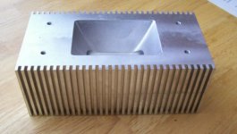
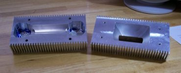
Here is a shot showing the two halves. The unit uses a double ended 250 watt HID bulb. The recess for the bulb cylinder is not round shaped like the outer surface of the bulb but is parabolic in shape in an effort to reflect more of the light out straight.
The focal point for the small parabolic reflector behind the bulb is nearer the rear of the light element and the focal point for the main front reflector is based on the front of the bulb element nearer the LCD.
The focal point for the small parabolic reflector behind the bulb is nearer the rear of the light element and the focal point for the main front reflector is based on the front of the bulb element nearer the LCD.
Attachments
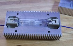
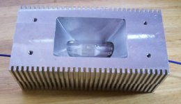
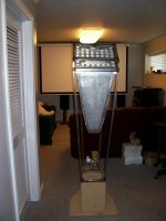
And here is the final shot with the whole thing together. This assembly will bolt to a flange welded onto the main deep parabolic reflecter.
There is little or no room for air circulation and my hope is that much of the heat will be absorbed and radiated into the heatsink.
There is little or no room for air circulation and my hope is that much of the heat will be absorbed and radiated into the heatsink.
Attachments
Hi Rox,
Good to hear from you. This is a one-off and would be very expensive if I made them for others. It is about 80 USD for the materials alone not including engineering and machining time.
If I had my own CNC machine and shop I might make a few at cost for forum members but I don't have the facilities.
However, If you can get the CNC machining done and the materials I can do the solid modeling and the CNC programming for you for free. If it isn't too complicated. IF you wanted a spherical reflector it would be real easy.
This design required me to use both Autodesk Inventor and Solidworks because neither program could do everything that I needed. I had to bounce the file back and forth between the programs to get the intersecting parabolic curves to intergrate with the other surfaces.
Then I imported a solid model into FeatureCAM to drive the tool paths for CNC programming. Our machines at school don't have a lot of memory in the controllers and because I am time limited the machined surfaces are not as good as could be done in ideal circumstances. So I will have to do some hand sanding and polishing.
Fortunately aluminum can be worked rather easily.
I think that now is a very good time to do a quick check before you get too far down a road you can't follow. Strike the ark in the lamp with it all bolted together in the holder/reflector. Set it up so that the thing is very close to the deep reflector and there is not much air circulating. Leave it on for a couple of hours if possible. I suspect you will want to get fancy with the heatsink if it will even work at all. I am not all that sure that the Aluminum will be able to dissipate enough heat through all the metal quickly enough. Have you tried it all loose-fit just to see how hot it gets yet?
Stocker,
I haven't yet had the whole thing together yet so I don't know how hot it is going to be but the aluminum should work just about as well as anything at getting the heat out.
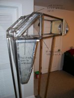
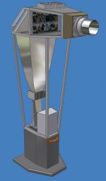
This whole thing will be suspended vertically in free air so there will be a lot of surface contact with the free air. I have provision for a fan if it is necessary.
Here is a picture again of the design if you haven't been through the whole thread. I'm expecting to keep the lower part of the frame open to free air. I think my biggest concern is going to be keeping the interior of the reflector from getting too hot.
Anyway, I have an idea for some fan cooling if heat is going to be an issue.
I haven't yet had the whole thing together yet so I don't know how hot it is going to be but the aluminum should work just about as well as anything at getting the heat out.
This whole thing will be suspended vertically in free air so there will be a lot of surface contact with the free air. I have provision for a fan if it is necessary.
Here is a picture again of the design if you haven't been through the whole thread. I'm expecting to keep the lower part of the frame open to free air. I think my biggest concern is going to be keeping the interior of the reflector from getting too hot.
Anyway, I have an idea for some fan cooling if heat is going to be an issue.
Attachments
hot design!
It depends on convection to remove heat from the reflector.
Unfortunately, I think it will work as a very efficient convection oven on the inside. All of the selective plastic films depend on some cool airflow to keep them from melting, but all they would see is a steady flow of super-heated air rising from the lamp area.
I think it will work a lot better if you have cool air flowing in at the top of the reflector (between the reflector & filters), and then pulled out around the sockets at the bottom. That would reverse the airflow, so you would have much less heat transfer up toward the filters.
Black anodize or lightly black paint the outside for more heat transfer into the air.
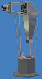
This is my latest idea in an attempt to stay totally passive with no noise generated by the projector.
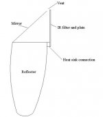
THe picture shows the large parabolic reflector bolted to the frame. My idea is to leave the large end of the reflector totally open and have a large slotted vent right at the top of the housing for the hot air to escape.
There is a slot about .75 wide and 13 inches wide that is not visible in the picture. Then I will make side sheilds out of very dark plastic to absorb stray light.
The IR film will be on a vertical acrylic or polycarbonate pane which acts as a barrier to keep hot air away from the LCD.
Attachments
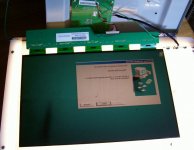
OK, I stripped my proview LCD monitor today and here are some pictures.
I rigged the LCD up on a small light box so I could see it's image orientation in relation to the connectors and logic circuits. You may be able to make out two green wires that are connected from copper ears on each side of the driver board to the metal controller board housing.
These are ground planes that must be grounded for the thing to work.
Attachments
Hezz,
I've been following your project for quite a while now, and I wish all success upon you.
Your design concept is fabulous--way to get "out of the box!"
But, I'm concerned about your safety with the heatsink idea.
I made a remark very similar to yours at LL a while back, and no one said anything, but I dug a little deeper and found this:
http://www.optiforms.com/4000services/4100opticalCOATINGS/41401ocREFLECTIVITYmetal.html
If I understand this correctly, polished AL is VERY REFLECTIVE of IR energy, and therefore, would not make for a good heatsink, hence dichroic coatings.
If I'm wrong, great! But I think you should mull it over a bit.
Boyd
bvlad,
Thanks for the input, you are correct in saying that highly polished aluminum reflects most IR. For that reason I have decided to use an IR film and keep the reflector housing open instead of sealed.
My goal will be to ancor the IR filter and it's plastic heat sink to the aluminum reflector on one edge so that heat can conduct from the IR filter and plastic shield into the aluminum.
I expect that the heatsink reflector will get pretty hot not from IR radiation but from slow convection. I may have to come up with a way to use forced air through the bulb housing and I have some ideas in that regard.
I will post a sketch of what I have in mind so that you can see what I mean.
Attachments
That is going to be my next approach if it turns out that things are running too hot. I will drill a bunch of small holes into the lower bulb housing between the heat cooling fins in areas that are the least likely to leak out light.
Even so, because of the tight fit of the bulb in the housing it will not allow a lot of air to flow around the bulb no matter how much air can pass into the lower bulb housing.
Anyway, forced air directly around the bulb is not necessarily a good thing because too much cooling at the wrong moment can cause the glass to burst. As long as the temp stabolizes at a reasonable temperture. That is all that I am concerned about.
Also the over simplified sketch in the above post does not show several slots that are around the parimeter of the large end of the reflector so it has several paths to intake cooler air. It's just that at this point all those are close to the large end of the reflector and there is no low impeadance air flow path all the way from the bulb housing up to the top air vent.
My feeling is that the lower bulb housing could run rather hot as long as I have a way to deal with the plastic coating on the wire leads so they don't melt and get shorted out on the bulb housing.
What I need are some short ceramic tubes that I can insert the wires through and can function as a high temperture insulater to protect the system from grounding out in the event of the wires plastic insulation getting too hot and melting.
As Guy has pointed out, it would be ideal if I could draw in cool air from the top over the IR filter and suck the air as it gets hot down and out of the bottom of the bulb housing. However, I don't see any practical way that I can do this where it would get enough air flow to be effective.
There is only going to be a small amount of air that can pass through the bulb housing.
I think I may be able to mount the IR film on the inside of the plastic heat shield where it will be in contact with both the heat sinked plastic heat shield and a flow of cool air that will be between the IR filter and the fresnel and LCD.
I think that even if I have no fan cooling for the light engine I may have to use one low RPM fan to draw cool air between the Fresnel/LCD and the IR filter/heat shield.
Today I have been mulling over some new design concepts for cooling. I would have liked to have kept this projector a totally passive design but I am unsure if that is practical or not. Especially for the cooling of the LCD.
In order for the LCD to be reliable in the long term it needs to stay below 100 degrees F.
After thinking about some cooling methods for the LCD I could not come up with any ideas that I thought were adequate within the frame that I had made.
Then I spent a couple of hours modeling on the computer and this is what I have come up with.
The new design involves the use of two quiet slow turning fans to draw cool air in between an air space between the plastic heat shield and IR film and the fresnel and LCD. In order to keep this thing quiet I may opt for two 120 mm quiet computer fans turning at around 400 - 500 RPM.
The design also includes a fan duct that blows a small amount of cool air into the bottom of the bulb housing through two 1 inch diameter holes. There is a certain amount of restriction so not a lot of air will being moving across the bulb but it should be enough to keep things cooler than without.
Attachments
- Status
- Not open for further replies.
- Home
- General Interest
- Everything Else
- The Moving Image
- DIY Projectors
- 17 inch 16:9 assault on high end project