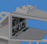
Here are some closer up pictures of the design model. On the top of the frame there is a plastic air dam and fan mount that acts to suck air out of several holes in the top of the LCD mounting frame. My goal is to get an airtight seal here so that the air will be forced to be drawn from the lower holes in the bottom of the LCD mounting frame.
Attachments
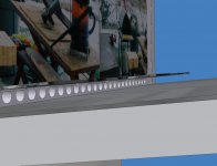
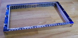
And another one showing the bottom air hole inlets from another angle.
The inlet holes are ninty degree passages which are essentially holes drilled from two sides of the LCD mount. The cool air will come in under the LCD driver circuits and have some cooling effect for them also.
The inlet holes are ninty degree passages which are essentially holes drilled from two sides of the LCD mount. The cool air will come in under the LCD driver circuits and have some cooling effect for them also.
Attachments

Hezz,
Lookin' good!
I was very tired when I wrote that last post, and didn't put very well what I was concerned about. I was actually very impressed with your passive cooling scheme, and believed that it work from the standpoint of the LCD--by sheer distance from the bulb if nothing else.
What had me worried was the tight confines of the (beautiful) bulb housing. Have you powered it up yet? If so, and it works fine, then I'll go back to mumbling in the corner
It is here that I was worried about polished AL and IR reflectivity--and convection, and, well, just plain too much heat for so small a space. I hope I'm wrong, but felt I had to throw in my .02
Cheers,
bv
bvlad,
Actually I'm glad that I got some feedback regarding heat issues. It has forced me to come up with a better design.
I have now got the bulb housing and reflector roughed in and I am working on the LCD mount. In the end I have come up with a better design than my first solid model which should have better cooling abilities.
I am going to see how hot things get with nothing but a passive cooling initially because I would rather have no sound or noise generated if it is possible to do so.
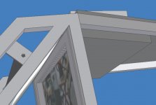
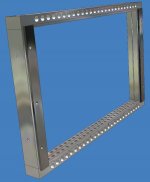
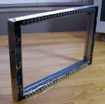
Here is a model of my LCD mount mechanism that I am building. The way this thing works is that it is comprized of four parts that bolt together. There is a slot in the middle of the frame which runs the inner circumfrence and is for capturing and holding the fresnel lens straight and in place. It also holds the fresnel about a half an inch away from the LCD so that the ridges in the fresnel are out of focus.
The LCD mounts in a shallow recess and has cutouts for the logic ribbons. Two thin aluminum plates hold the LCD in place so it can't fall out of the mount.
The frame is designed so that a lot of holes allow air to circulate and vent up and out. Either through natural convection or forced air.
Thus the LCD will have both a lexan and IR film isolator and the fresnel will also act as an heat isolator which is cooled on both sides. The air flow will also cool the thin plastic IR film which will be able to conduct heat out of the lexan shield into an aluminum heat sink block.
THe frame is made from aluminum which also allows heat build up on the LCD and fresnel to bleed off into the aluminum and then the steel frame.
Actually I'm glad that I got some feedback regarding heat issues. It has forced me to come up with a better design.
I have now got the bulb housing and reflector roughed in and I am working on the LCD mount. In the end I have come up with a better design than my first solid model which should have better cooling abilities.
I am going to see how hot things get with nothing but a passive cooling initially because I would rather have no sound or noise generated if it is possible to do so.
Here is a model of my LCD mount mechanism that I am building. The way this thing works is that it is comprized of four parts that bolt together. There is a slot in the middle of the frame which runs the inner circumfrence and is for capturing and holding the fresnel lens straight and in place. It also holds the fresnel about a half an inch away from the LCD so that the ridges in the fresnel are out of focus.
The LCD mounts in a shallow recess and has cutouts for the logic ribbons. Two thin aluminum plates hold the LCD in place so it can't fall out of the mount.
The frame is designed so that a lot of holes allow air to circulate and vent up and out. Either through natural convection or forced air.
Thus the LCD will have both a lexan and IR film isolator and the fresnel will also act as an heat isolator which is cooled on both sides. The air flow will also cool the thin plastic IR film which will be able to conduct heat out of the lexan shield into an aluminum heat sink block.
THe frame is made from aluminum which also allows heat build up on the LCD and fresnel to bleed off into the aluminum and then the steel frame.
Attachments
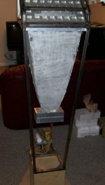
Here is a digital photo of the projector in it's current state. I have bolted the bulb housing and reflector to the main parabolic reflector.
I have yet to install the bulb and wire it up as I am waiting to finish the LCD mount. Actually, the outer glass housing on my bulb was broken at some time during my building process. The glass is still generally in place though and I'm hoping that the bulb will still fire up and the light will work. None of the element or the leads were damaged.
I sand blasted the outside of the big parabolic reflector to clean it up a little but the sandblaster was low on sand so it didn't do the best job. No matter though as the outside of the main reflector will be painted black.
Frankly, there is a lot of hand work to do to get the insides of the reflectors really smooth and shiny. But I think that I will be able to tell if it is going to work when I fire it up even though the light output will be a little reduced.
My big hope at this point is that the LCD will remain cool enough without fans to help in the cooling process.
Attachments
Lookin' good, Hezz!
I do think you'll be able to pull this off eventually, due to the flue-like nature of the parabolic section. Glad to hear that you're rethinking the bulb housing.
Best of luck!
Boyd
I do think you'll be able to pull this off eventually, due to the flue-like nature of the parabolic section. Glad to hear that you're rethinking the bulb housing.
Best of luck!
Boyd
Guys,
Today I installed the bulb into the bulb/reflector housing and rigged up an extension cord and lite the light.
It seemed to flicker a little but then slowly came up to full brightness.
Everything seems to be working and I left the light on for about twenty minutes (which was all of the time I had) to try and let the reflector housing get up to a stable temp.
The area next to the first surface mirror got quite warm but the hot air was chimneying right out of the top and the lexan heat shield was not even getting hot. I would say it was around 110 F.
However, my guess is that when I make the reflector more reflective it will transmit more of the IR.
THe bulb housing eventually got about 150 degrees and no hotter. IT was good and warm but not so hot that I couldn't put my whole hand around it and leave it there. I did not actually record an accurate temp. but I think it was around 150 degrees F.
When I have more time I will leave it on longer and record an accurate temp. at several locations.
But I think that it was pretty stabalized and right now it is looking pretty positive to be an all passively cooled design with no fans. I will be very happy if I can keep it dead quite.
White Rose sells the exact mirror film (plastic sheet) that is used in RPTV's. It can be mounted on any shape and then heat shrinked into a drum tight surface.
Just so you know.
Just so you know.
Quick update,
Thanks for the informationon the IR film. Eventually I will probably get some but first I want to see how hot things get without it.
A couple of days ago I finished my LCD and fresnel mount. My task now is to get it to fit into the frame. I spent some time today welding and grinding on the frame. As it was a pretty warm day.
It looks like because my frame angles are less than perfect I am going to have to mill a little bit more material off from the outside edges of the LCD mount to get it to fit into the frame.
You have worked a lot on various aspects. Our approach has been to complete the projector first and then improve upon by proper adjustments with reference to the image on the screen. We have summerised our work on our web page, the details can be seen by clicking the link below:-
http://www.drtsolutions.com/Projector.htm
http://www.drtsolutions.com/Projector.htm
Hey, that looks like the rendering... good job.
Did you leave the lamp lit for a long time (hours) yet? I am glad for you that it seemed to be cool enough in a short test anyway.
Did you leave the lamp lit for a long time (hours) yet? I am glad for you that it seemed to be cool enough in a short test anyway.
Stocker,
I have the whole thing torn apart right now as I am working on the frame so I haven't done any long term test for heat. My short term tests made me feel that totally passive cooling may be possible. It will be the LCD that will be the issue.
Right now I'm trying to figure out how I am going to mount the LCD logic circuits and driver board.
Finally I got a warm day today to work outside,
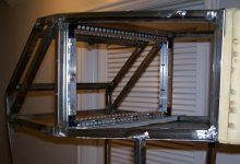
I spend several hours working on the LCD mounting frame and getting it into the projector frame. I had to do quite a bit of weld grinding to get the LCD mounting frame into the less than perfectly square main frame.
I also build be LCD panel circuit board mount and the controller card will mount on the under side of the frame on a aluminum panel.
Here is a snap shot. Now I think what I have got to do next is cut down the fresnel and put it inside the LCD mount. I am still trying to think of a good way to cut it up without scratching it or cracking it.
Attachments
cutting an acrylic fresnel
My Dremel with a thin abrasive cutting disk worked great. I put some blue easy-release masking tape on the smooth side to mark the edges I wanted to cut. Very easy, but it does make a real mess with all the tiny bits of acrylic everywhere. Do it outside or in a garage you can sweep up easily.
You also need really good eye protection, like goggles. When you are done, take a shower and change your clothes before you touch your face. Otherwise it is likely you will get acrylic dust in your eyes: Very painful and hard to get out.
Guy,
Great idea. I don't have a dremel but I bet I could use my die grinder with the proper cutting wheel or disk. This sounds like the best idea so far. I tried a test cutting with a jigsaw but it makes too many cracks in the edges. I don't think that method is safe. I can use a bandsaw at school but I will have to slide the fresnel around on the surface which may get scratched. I guess I could put a protective cover on it but then I have to deal with getting off the adheasive.
Are you using an abrasive wheel or some kind of metal wheel with cutting teeth. My only concern is that the die grinder runs at very high RPM.
- Status
- Not open for further replies.
- Home
- General Interest
- Everything Else
- The Moving Image
- DIY Projectors
- 17 inch 16:9 assault on high end project