It's an abrasive disk that is about 1 mm thick and about 1 inch in diameter. The Dremel has a built-in speed control, but I ran it at full speed. You can cut out some paper to fit 1/2" back from the cutting lines, then use the masking tape to fasten it to the smooth side of the fresnel. The paper will protect the surface as you move it around on your bench, etc.
I think you could use a thin abrasive disk with a fine grit on a die grinder. You just need a steady hand so you don't turn the grinder out of perpendicular and catch the edge of the wheel on the fresnel. It would be a good idea to put the fresnel on a clean bench (with the paper-protected side down), so the line you want to cut is just over the edge of the bench surface. Then put a clean cloth, a piece of wood, and something heavy on top of it to hold it in place. Use the Dremel, grinder, etc. to cut with the leading edge of the disk moving down into the cut. That way the bench will support the fresnel and stop it from flying around.
I think you could use a thin abrasive disk with a fine grit on a die grinder. You just need a steady hand so you don't turn the grinder out of perpendicular and catch the edge of the wheel on the fresnel. It would be a good idea to put the fresnel on a clean bench (with the paper-protected side down), so the line you want to cut is just over the edge of the bench surface. Then put a clean cloth, a piece of wood, and something heavy on top of it to hold it in place. Use the Dremel, grinder, etc. to cut with the leading edge of the disk moving down into the cut. That way the bench will support the fresnel and stop it from flying around.
Guy,
Thanks for the info. Today I bought a package of five 3 inch abrasive cut off saws. They are about 1.5 mm thick and are fiber reinforced. Although they are for steel and aluminum they should work for plastic as long as they don't load up too much.
I think I may chuck them in my drill which has more power and will limit the speed to around 1000-1500 RPM. Instead of 8,000-10,000 RPM of the die grinder.
Good idea. They are probably not rated for 8000 RPM. You don't want one of those flying apart when you are in the same room!
The Dremel disks do fly apart at the least bit of sideways stress, but they are so light that the air resistance slows them down by the time they hit anything. I just wear safety glasses usually, so I don't get a piece of crud in my eyes. I went through five or six cutting a stainless steel quiche mold for my reflector. I think I cut all four sides of my two fresnels with just one disk.
The Dremel disks do fly apart at the least bit of sideways stress, but they are so light that the air resistance slows them down by the time they hit anything. I just wear safety glasses usually, so I don't get a piece of crud in my eyes. I went through five or six cutting a stainless steel quiche mold for my reflector. I think I cut all four sides of my two fresnels with just one disk.
The variable speed hand drill worked great with the cut off wheels.
I noticed that they were rated for 24,000 RPM so they are made for high speed but since I didn't have a full face safety mask I didn't really want to run at such a high speed.
Also, I thought it might be easy to slip at higher speeds and scratch up the fresnel. With the 3 inch fiber reinforced cut off blades it only took me about five minutes to cut out the fresnel. I now have it mounted in the LCD mount and in the frame.
I may have the projector ready to try out tonight except that now I need to order a few parts for my HTPC which has been down for six months since I robbed the CPU and memory out for another computer. I haven't been using it since it is a dedicated use HTPC for the projector.
I will order a CPU on e-bay if I can find one for it.
Also, I have a lot of work to do on the light engine polishing the reflector and mirror. I am going to need to get another smaller right angle die grinder and a collection of abrasive pads in finer grits.
I will post another picture when I get it all assembled with the necessary guts for projecting a picture.
mirror
I have serious doubts about your mirror. Rays from each pixel will strike an area on the mirror surface about 1/2 the diameter of the projection lens before being reflected into the lens. The lens will then refract all of those rays to a single pixel of the screen image. If your mirror is not perfectly flat over that area, then the rays will not converge to the same point on the screen.
I know that polishing a lens surface to be perfectly flat is just as difficult as getting it to a particular curve. I don't see how you are going to get your mirror surface to be all that flat without a harder perfectly flat surface to grind against it.
You can always just buy a first surface glass mirror to attach to your metal mirror surface.
Guy,
I don't know, it can be gotten very flat but it will take a lot of time. At this point though I am more worried about the parabolic reflector. Like you said it is easy enough to glue a mirror to the aluminum.
Last night I fired the thing up and the LCD is working just fine. But the light through the system is dismal. I knew it wouldn't be good because I have yet to condition the reflectors. At this point the big reflector is far more diffusive than reflective. But I thought that I would at least get a dim image. I did but it was too dim to make out the outer edges of the screen.
Also I am going to have to shim the lens mount out about 3/4 of an inch. Because my final LCD position in it's mount is somewhat closer to the lens than I had originally planned.
It isn't columnating the light as I had anticipated but then again it is hardly even polished. So I may line it with reflective mylar to test it and see if the increased reflection will prove out my concept.
Also I left the thing on for about an hour and a half and the bulb housing got a lot hotter than last time. Not too hot to melt wires but too hot to touch. For some reason the ballest was humming and the light was making noise that it did not the first time.
The first time I fired up the light and ballest were dead quiet now there is too much noise and the tranformer is getting too hot. As far as I can tell it is wired up the same. I even tried reversing the bulb polarity thinking that is was possible there was more resistance one direction than the other. It didn't make any difference.
I guess this is why guys are spending money on the electronic ballasts.
The LCD mechanism stayed reasonably cool as far as I can tell so this is positive and makes me think that the silent passively cooled goal is possible.
At this point it is the light engine that worries me.
Dear Hezz,
You are doing wonderful work. There are many experienced and knowledgeable persons who will solve your problems. In case the problem is not solved to your satisfaction, you may think of adopting our approach. We concentrated on the final image right from the beginning and created the set up backward. Every stage we kept provision for adjustments and fine tuning and now our results are excellent, even appreciated by experts in the field. The optical circuit in the projector is quite tricky though appears simple. Whenever you find free time, please go through the content of our web page.
You are doing wonderful work. There are many experienced and knowledgeable persons who will solve your problems. In case the problem is not solved to your satisfaction, you may think of adopting our approach. We concentrated on the final image right from the beginning and created the set up backward. Every stage we kept provision for adjustments and fine tuning and now our results are excellent, even appreciated by experts in the field. The optical circuit in the projector is quite tricky though appears simple. Whenever you find free time, please go through the content of our web page.
Dear Ramkishan,
Thanks for the positive feedback. I have seen your projector and it looks really good. At this point I feel like I have been punished for trying a different light engine concept but hopefully I may get it to work.
If not I can always redesign with a more standard setup.
Thanks for the positive feedback. I have seen your projector and it looks really good. At this point I feel like I have been punished for trying a different light engine concept but hopefully I may get it to work.
If not I can always redesign with a more standard setup.
I have been working at the lower bulb housing reflector and have the uppermost part polished. It is much more reflective and shiney than before.
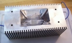
Here is a picture of the reflector. Though the surface is quite reflective I don't believe that I will realistically be able to get this curved surface really true. You can see a bit of the blurriness in the reflectied image of the bulb.
I am quite certain that I can eventually get the large parabolic reflector about this quality. I hope that it is enough to allow for the projection of an image.
Attachments
Nice lampholder. If it gets too hot, I am sure you can manfacture a larger add on heatsink to dissapate some more heat and not have to go down the route of forced cooling and stay passive. If it gets too hot then you might want to put a heat guard on it!
Hi Nads,
I think that it will be OK because it still is not too hot to burn. If you were to hold your hand around it it would scald you but a momentary touch will not cause a serious burn. I estimate that it is around 180 degrees F.
I've also done some more polishing of the main mirror and it is showing a much better reflected image than before.
It turns out the parabolic reflector will be too difficult to polish because of the surplus metal I made it from. So I have ordered some 98 percent reflective mylar to line the parabolic reflector for the next test.
This should give me enough of a quality reflective surface to proof out the design and see if it is a feasable solution.
I have just got my HTPC rebuilt to drive the projector after scavenging parts from the old melted down unit from last year.
Hopefully within a week I should have some images projected on the screen. If any of the results are good enough to post I will snap some pictures.
Update,
I have done some more testing on this projector design and it now appears that the light engine design has some flaws that will render it unuseable for a projector.
There is some good news however. I have been able to keep the projector cooled with totally passive means. Although the bulb housing gets hot the LCD and other important things stay quite cool.
I have polished the first surface mirror to a higher degree and also the bulb housing reflector assembly.
Because I had made the big parabolic reflector with surplus aluminum to cut down on it's cost (I wasn't sure if I could even build it) it would have required too much time to hand finish to a high degree of shine. So I ordered some 98% reflective mylar film and lined the reflector with this. It was pretty much impossible to get the mylar glued down perfectly flat with the adheasive that I used. A high temperture silicone gasket material.
I wanted the glue to be able to take any heat that was generated in the parabolic reflector.
In any case, the parabolic reflector with the mylar was much more reflective than without but is far from what it should be in terms of surface uniformity due to some air bubbles and wrinkles that I could not get out.
I know that the reflectors performance would be impaired but I figured it would be enough to see if the reflector is working. Unfortunately the reflector does not properly collimate the light and I now have a couple of theories as to why it is not working.
The first has to due with the rectangular cross section of the reflector. This reflector was designed this way for two reasons. One, because I wanted a light output that was roughly the same shape as the LCD monitor. Second, it made it possible to make.
Typically most parabolic mirrors are of a circular cross section. This would have been too large to deal with for the size I was making. Also it would have been very expensive to make.
The jest of why I think that my parabolic reflector is not collimating enough light has to due with light from the bulb element that strikes the interior reflector walls at oblique angles which is most of the light.
With a parabolic mirror with circular cross section more of the oblique light rays are bent in towards the middle of the reflector so a lot of light stays in a straighter line. The problem I seem to be having is that too much of the light is being sent out in a wide pattern at the mouth of the reflector. I can only surmise that this is because that oblique light rays from the bulb are seeing a straight wall and so are not bent in towards the center of the reflector.
In any case, the light output is too dim to be useful which is unfortunate as the projector is totally silent except for the ballest hum which can be rectified with a better electronic ballast.
As such this frame design is gong to be scraped and I will use the lens and LCd mount and LCD to build a more conventional design. Now that I have my HTPC back up and running I would like to at least get someting projected on the wall.
Bummer !
These are the uncertainties that one encounters when experimenting. I have been following this thread with much enthusiasm and I'm disapointed for you.
Very nice of you to share your experiences as the project progressed.
This is the spirit of DIY.
🙁
These are the uncertainties that one encounters when experimenting. I have been following this thread with much enthusiasm and I'm disapointed for you.
Very nice of you to share your experiences as the project progressed.
This is the spirit of DIY.
🙁
kludge
Sorry to hear it. It really is quite pretty.
Before you totally scrap it, consider that most people only get about 20% more light from their spherical reflectors. You could run your current setup just by adding a condensor fresnel to take light directly from the lamp arc and refracting it to be parallel going into your field fresnel. That should be plenty bright for viewing in a darkened room. When you get inspired, then you could modify the light engine to fit one of those Ikea napkin holders in there, or a real glass reflector from one of the DIY shops.
I know it's not what you wanted, but this just goes to show that everybody should build a flexible optical bench version before they commit to many (hundreds?) hours of work. Especially on a new design.
I still wonder if your lamp would have overheated and died after a few hours without any fan-driven air around the lamp, or if the convective airflow would have been adequate to keep it cool enough.
Remember: If your experiments never fail, then you're just not trying hard enough!
Guy,
Thanks for the kind words. As I look back in the threads I remember having the idea to use a small condenser lens inside of the reflector.
However, after having built this beast and and getting the rest of the HT stuff together I think that I want to gravitate towards a ceiling mounted design eventually.
So I think I am going to cut up the current frame and use part of it along with the metal to built a smaller design. I have some design ideas all ready in the works.
cooling
Even if you do change to a more conventional design, please keep in mind that using the right components can give you a cool and quiet projector. I am using a very nice hot mirror from Rosco to keep IR away from the fresnels and LCD, so a single well-placed fan is all I need to keep everything cool. With the right cushioned mounting and some sound absorbing baffles, that can be very quiet.
Even if you do change to a more conventional design, please keep in mind that using the right components can give you a cool and quiet projector. I am using a very nice hot mirror from Rosco to keep IR away from the fresnels and LCD, so a single well-placed fan is all I need to keep everything cool. With the right cushioned mounting and some sound absorbing baffles, that can be very quiet.
Today I removed the big parabolic reflector and bulb housing with the light running and shined it on the ceiling. What I got was a near perfect rectangular shape of bright light. So it seems that the reflector is collimating the light reasonable well.
I then remembered that I had the old LL fresnel that was something like 30 inch FL and I installed it as a rear condenser fresnel. This improved the light output by some small amount but not enough to be effective to watch. The bulb is about 35 inches away from the rear condenser fresnel which I just installed. So the bulb sits about five inches back from where it should.
In a darkened room which is not completely dark (daytime dark with all of the blinds closed) I can see the screen image in outdoor daylight scenes but the colors are very washed out. Dark scenes are nearly imperceptable except for bright objects.
Also, regardless of the brightness issues I don't seem to be able to get a good sharp focus. I'm sure that part of this has to do with the light engine not being dialed in but I think that part of it is the lens. I remember testing this lens and thinking that it was not very capable at really good focus but because my test lighting setup was poor I assumed it was just poor back lighting.
I have a feeling it is partly due to the lens. Because of the non adjustable nature of this design I think the only way to improve it is to get exact FL fresnels but I still unsure if that would be sufficient. Also it seems impracticle since it is not likely that I could get exactly the right sizes.
One other thing I might try is a sheet of reflective polarizing film. If I seal off the light engine so light can only escape at the hot air vent it might increase the light output a little. At this point anything that helps would be useful. A small increase in light output may make it watchable in total darkness. Tonight I will try and watch in a total dark room and see how watchable the image is.
I have learned a lot from this design and the next one will be more conventional with a better lens and LCD and a more tested light engine concept. However, This think is real quiet. My HTPC is making a lot more noise.
Update,
With the room as dark as I could get it the projected image is watchable but significantly too dark to see details. However, with the room darkened I have been able to pinpoint a lot of stray light problems that have been reflecting out onto the image.
I have taped them over with duct tape as a temporary fix but the room is still not totally black because of all the stray light leaks from the open frame.
At least I was able to watch Star Wars. I have the screen at only about 90 inches to conserve light from the intended 106.
It also seems that I was wrong about this lens. It seems to be working better than I had thought. Once I had the room darker and put on my glasses I was able to focus the lens a lot better. Down to where I can see the spaces between the pixels. Even out to the corners of this 15.4 in widescreen LCD the focus is adequate for watching movies. There is still some less than razor sharp imaging going on but it is adequate to read the icon writing on the Windows XP icons. It would probably become irritating for internet cruising.
When watching with the original widescreen aspect ratio in PowerDVD the blank bars at the top and bottom of the screen keep the image in most of the len's acceptable field of view.
It looks like the real weakness is the light engine which is not bright enough. After two hours of running a movie the bulb housing got about 200 degrees F but everything else seems to be OK. Also, since I have taped up so many of the stray light leaks the projector does not cool quite as well as it did before when it had so many light and air leaks. But it still seems respectable and is running without a heat problem.
I may try a reflective polarizing film if I can get some cheap to see if I can gain any brightness. Other than that I think that I will start saving to buy parts for the next projector project.
I'm looking at a 19 inch widescreen Samsung LCD monitor with a really nice picture and 8 millisecond response time. I think that it will work with the new Lumen Lab Pro lens and this monitor can be bought for about 299 USD at PC club. The model number is VIEWSONIC LCD 19" WIDE 8MS SPK VA1912WB and it has 500:1 contrast ratio. Here is the link:
http://www.pcclub.com/product_details.cfm?itemno=A4692023
Looks like Tiger Direct has it for 269 USD. Even better deal.
If I get motivated I will post some screen shots but since the brightness is so low I would have to do a still screen timed exposure with 35mm film. I'm not sure if I want to do it and I don't know if my digital camera will be able to take the low light pictures.
nothing wrong with your LCD
If I were you, I wouldn't give up on the 15.4" LCD. It already has the resolution you need for 720P HDTV, and it works with your lens. All you need to do is to fix the light engine problem.
That problem is that the lamp is too far from the condensor fresnel. Without the reflected light, the inverse square law applies. The 790 mm long fresnel puts the lamp so far away that not much of the light is falling on the fresnel.
I would get a 200-220 mm fl fresnel and move the lamp arc up to that distance from the fresnel. You should get 790/200 squared more light: 15 times brighter!
Hey Guy,
Thanks for the feedback. I actually have a 220mm fresnel that I could use but the frame would require a redesign. However than is certainly possible.
Also, in spite of the fact that the light engine is a hybrid design other than the low light problems there seem to be some pluses which lead me to think that it might be wise to continue using this topology for further experimentation.
I have also come up with a light recycling idea that is rather simple to initiate.
Some pluses of the hybrid design are that the lighting is very even all across the LCD.
I will posts some sketches of the ideas that I am having. Actually I think that I could put in a condenser fresnel with a nine inch focul length and put the bulb at about ten inches away without any redesign of the projector frame.
The light recycling method would only require a piece of reflective polarizing film and one quarter wave retarder film and one piece of quarter inch think acrylic sheet.
- Status
- Not open for further replies.
- Home
- General Interest
- Everything Else
- The Moving Image
- DIY Projectors
- 17 inch 16:9 assault on high end project