Zkusil jsem vyměnit zenerovy diody, ale stále nereguluje, na výstupu je stejně napětí. Prosím o pomoc, čím by to mohlo být? Mám k dispozici i trafo s výstupním napětím 2x 40VAC.Dobrý den, děkuji za odpověď. Použil jsem rozložení stránky 134, #2,677. Omlouvám se za mě anglicky.
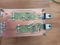
Zde jsem použil transformátor 2x30VAC a zenerovy diody 8V2, zkoušel jsem i 7V5 a stále nereguluje. Chci tento zdroj použít v kombinaci s 2x40VAC transformatorem pro zesilovač Apex SR50, FH9, R.Elliott P3A a jim podobné. Děkuji z jakoukoliv radu a pomoc.
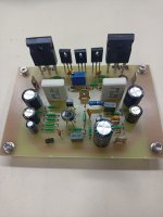
Ještě přikládám fotku Apex FH9, ze začátku se mi zdal, že hraje vysoko a ostřeji, dnes po nastavení a propojení s Apex TB1 užasný velký zvuk. Děkuji panu Milemu Slavkovičovi a vám všem. Provozuji s IRF9540/ IRF540. Testováno i s IRFP9240/ IRFP240.
Attachments
I tried replacing the zener diodes, but it still doesn't regulate, the output is the same voltage. Please help, what could it be? I also have a transformer with an output voltage of 2x 40VAC.
Here I used a 2x30VAC transformer and 8V2 zener diodes, I also tried 7V5 and it still doesn't regulate. I want to use this power supply in combination with a 2x40VAC transformer for Apex SR50, FH9, R.Elliott P3A amplifier and similar. Thanks for any advice and help.
Attachments

I am attaching a photo of the Apex FH9, at first it seemed to play higher and sharper, today after setting up and connecting it with the Apex TB1, it sounds great. I thank Mr. Mile Slavkovič and all of you. I operate with IRF9540/ IRF540. Also tested with IRFP9240/ IRFP240.
Thank you

HI Please share AX11 one pair Schematic and pdf for Diy want to make thisAX-11, two pairs 2SD1047/2SB817
AX11, one pair BD249C/BD250C
Hi !
I present to you a class AB amplifier made according to the Apex A40 scheme.🙂

I present to you a class AB amplifier made according to the Apex A40 scheme.🙂
Hi Mikel1998,
you made a beautiful amplifier, congratulations!
I'm curious and would like you to describe me some parts that can be seen in the photo, in particular the PCBs (small pcb) on the right and left of the toroidal transformers and those on the rear with relay and black capacitors.
Thank you very much, 🙂
Marco.
Thanks !
I would choose to answer through a post, maybe I can help someone else. The pcbs on the right and left of the toroidal is drivers for the dc protection of the speakers.In the front part, the pcbs with potentiometers are controllers for the forced cooling system.On the left side (back) is a 3-channel selector that switches through a push button.
I hope I have provided enough details😆
- Home
- Amplifiers
- Solid State
- 100W Ultimate Fidelity Amplifier