Hi everyone!
Could you help me?
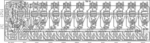
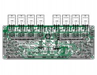
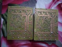
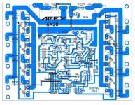
Assembled APEX PSU-10 for APEX A40 and for some reason the output voltage is not regulated. Rotating trimmer voltage does not change at all, on average 48-49V. The difference between + and - is approximately 0.6V.
Although if you measure it at the anode of the zener diode, then it varies from 7 to 17V. Although if measured at the anode of the zener diode (20V), then it varies from 7 to 17V depending on the rotation of the trimmer. Therefore, I am confident that the trimmer is in working order.
I already tried another trimmer, I thought maybe I didn't get a worker, everything also remains. The board is washed and clean. I checked all the details before soldering, selected similar characteristics in each shoulder.
All components are used as indicated on the board. Except for capacitors 10,000 microfarads. They were replaced by 20,000 microfarads.
Could you suggest what else to pay attention to?
Thank you in advance.
Could you help me?
Assembled APEX PSU-10 for APEX A40 and for some reason the output voltage is not regulated. Rotating trimmer voltage does not change at all, on average 48-49V. The difference between + and - is approximately 0.6V.
Although if you measure it at the anode of the zener diode, then it varies from 7 to 17V. Although if measured at the anode of the zener diode (20V), then it varies from 7 to 17V depending on the rotation of the trimmer. Therefore, I am confident that the trimmer is in working order.
I already tried another trimmer, I thought maybe I didn't get a worker, everything also remains. The board is washed and clean. I checked all the details before soldering, selected similar characteristics in each shoulder.
All components are used as indicated on the board. Except for capacitors 10,000 microfarads. They were replaced by 20,000 microfarads.
Could you suggest what else to pay attention to?
Thank you in advance.
Attachments
check usuals "errors" board continuity, transistors orientation, fake components...
solder in the evening and power up in the morning 🙂
solder in the evening and power up in the morning 🙂
Is there a load at the output of the power supply?
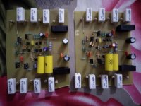
Yes, such indicators with load and no load. In addition, if turn on the amplifier, then a power skew may begin. And the amplifier starts to self-excite.
With another power supply, everything is ok.
Thanks, but I checked it first before writing a message here 🙂check usuals "errors" board continuity, transistors orientation, fake components...
solder in the evening and power up in the morning 🙂
Last edited:
Hi everyone!
Could you help me?
Assembled APEX PSU-10 for APEX A40 and for some reason the output voltage is not regulated. Rotating trimmer voltage does not change at all, on average 48-49V. The difference between + and - is approximately 0.6V.
Although if you measure it at the anode of the zener diode, then it varies from 7 to 17V. Although if measured at the anode of the zener diode (20V), then it varies from 7 to 17V depending on the rotation of the trimmer. Therefore, I am confident that the trimmer is in working order.
I already tried another trimmer, I thought maybe I didn't get a worker, everything also remains. The board is washed and clean. I checked all the details before soldering, selected similar characteristics in each shoulder.
All components are used as indicated on the board. Except for capacitors 10,000 microfarads. They were replaced by 20,000 microfarads.
Could you suggest what else to pay attention to?
Thank you in advance.
Use 12V zeners...
Thank you mr. Mile. What voltage range will be with 12V zener diodes? This will work for APEX A40?
Thank you mr. Mile. What voltage range will be with 12V zener diodes? This will work for APEX A40?
Set +/-40V...

Hello everyone, I want to make a 500W amplifier for my bass. Mile, which apex amplifier can be used?
Please take your pick:-
900W H-class PA Amp with Limiter
500W PA amplifier with Limiter
1000W Simple PA Amplifier
900W H-class PA Amp with Limiter
500W PA amplifier with Limiter
1000W Simple PA Amplifier
Thanks, I see that I can build a pair of B500 with 75 VDC each and feed two boxes (4x10 and 1x15) or 4 boxes (4x10 and
1x15) x 2. Respecting the impedance.
1x15) x 2. Respecting the impedance.
Hi,
I found two spare transformers 2x18V 250VA. Which design could be done with this two ? Any design about 100W that would run with such a low voltage ?
I found two spare transformers 2x18V 250VA. Which design could be done with this two ? Any design about 100W that would run with such a low voltage ?
- Home
- Amplifiers
- Solid State
- 100W Ultimate Fidelity Amplifier