maybe,yes. but we don't know until you post a PCB documents...
ok i put an image...tnx 44250
ax17 problem
hi a gain.in this link i put my layout file.plz check this for my mistake...i have in output 48 volt dc(psu is 50-0-50). dear friends please help me
hi a gain.in this link i put my layout file.plz check this for my mistake...i have in output 48 volt dc(psu is 50-0-50). dear friends please help me
An externally hosted image should be here but it was not working when we last tested it.
Last edited:
ax17 layout(have problem)
http://uupload.ir/files/j2x7_ax17.bmp
for see this pic copy this link and pate on browser search...dont chick directly
http://uupload.ir/files/j2x7_ax17.bmp
for see this pic copy this link and pate on browser search...dont chick directly
Last edited:
input gnd should be connected to the psu gnd. i don't know why C10 is connected from amp-output directly to gnd?
tnx 44250input gnd should be connected to the psu gnd. i don't know why C10 is connected from amp-output directly to gnd?
c10 and r29 connected in parallel to ground and output...
Hassan i have done a short google search "apex ax17" and found different examples for
layout, parts placement so on..
Only for example alex mm is one of the master in PCB design here.
Look here in the thread: #2918
100W Ultimate Fidelity Amplifier
You can see sgnd is connected to gnd via 10 Ohm resistor (ground lift), also Emitter R27/28 are connected together to Output.
I don't see that in presented file of layout? R27 is connecting Transistor Emitter to ground only.
You can also see in alex layout the 10 Ohm/3W-R29 is going from output to 47n- C10 and
than connecting ground, i think it should work as R-C network together, i've never seen it that way.
Could this work too, that way?
R28/R27 connected together with jamper....pcb is correctly...Hassan i have done a short google search "apex ax17" and found different examples for
layout, parts placement so on..
Only for example alex mm is one of the master in PCB design here.
Look here in the thread: #2918
100W Ultimate Fidelity Amplifier
You can see sgnd is connected to gnd via 10 Ohm resistor (ground lift), also Emitter R27/28 are connected together to Output.
I don't see that in presented file of layout? R27 is connecting Transistor Emitter to ground only.
You can also see in alex layout the 10 Ohm/3W-R29 is going from output to 47n- C10 and
than connecting ground, i think it should work as R-C network together, i've never seen it that way.
Could this work too, that way?
i confused abut ax17....
i see many pcb of ax 17...i check my pcb with schematic...step by step...every thing be ok....just i read in forum that c6 replace 1000uf/16v....and replace R21 whit 1/5k....but yet have problem....maybe my mistake..tommorow i check every thing again....a have problem too with fh11..but mr mail help to solve that..
CA14
Hi Mile
With respect to this circuit, there are amplifier manufacturers that use regulated supplies for the input stages and VAS, but in some cases, this is greater than that of the output stage and in others it is smaller, what is the criteria or what Search with these topologies ?.
Thank you
Hi Olaf,
The A14 is singing. I had a little trouble at first until I noticed that the input ground is not attached to anything. I installed a 5R6 resistor from input ground to PGND and all is well. This is quite a nice amp. Square waves are very sharp and the sound is clear with strong bass. Very nice.
can i use 50-0-50 psu for this amp?
ax17 is betete or it?
can i use 50-0-50 psu for this amp?
ax17 is betete or it?
I didn't build the AX17 so can't speak to that. I wouldn't use a +-50V supply for anything that doesn't have at least two pair of outputs.
R28/R27 connected together with jamper....
Ok, that comes in mind as i wrote here.
I also don't have build this AX17, but for SOA of 1943/5200 is max +/- 42V more safe
with 8 Ohm load only.
For Test add some power R of 10Ohm/5-10W in each supply line.
Have you connected sgnd to Pgnd now? as suggested, also a 4,7-10 Ohm R can be used to
connect it, sometimes helps.
You can also compare to Alex PCB to yours for differences.
Maybe your start with 50 volt was to high for any transistors?
Let us know your next steps of testing, so experienced members will help with more
advice.
very tanx that help me...im not in home...when come back do it and tell to you what happened...best wish for me and you.Ok, that comes in mind as i wrote here.
I also don't have build this AX17, but for SOA of 1943/5200 is max +/- 42V more safe
with 8 Ohm load only.
For Test add some power R of 10Ohm/5-10W in each supply line.
Have you connected sgnd to Pgnd now? as suggested, also a 4,7-10 Ohm R can be used to
connect it, sometimes helps.
You can also compare to Alex PCB to yours for differences.
Maybe your start with 50 volt was to high for any transistors?
Let us know your next steps of testing, so experienced members will help with more
advice.
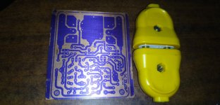
see post 11348....its my ax17 with 2 pair....full symmetrical...
https://www.diyaudio.com/forums/sol...mate-fidelity-amplifier-1135.html#post5827095
but i decide made one pair for test.....
i hope that problem be solve because i have such as your friend an teacher.
in left pcb 10r/3w is for zobel.
https://www.diyaudio.com/forums/sol...mate-fidelity-amplifier-1135.html#post5827095
but i decide made one pair for test.....
i hope that problem be solve because i have such as your friend an teacher.
in left pcb 10r/3w is for zobel.
I didn't build the AX17 so can't speak to that. I wouldn't use a +-50V supply for anything that doesn't have at least two pair of outputs.
i see that you are very active in forums.
whats your suggest for me....for a 200 watt (50-0-50 psu)wich apex bjt amplifier is beter?
ax14 with 2pair/ax17 with 2 pair/ax20/a23/a33/a40...wich one?
however i love made all of them.but i want your idea!
regards
Last edited:
hi again....today i connected a 10R/3watt resistant between ground and signal ground....and connect psu....no pupop....no noise...no hom...ax17 work properly...tnx a lot. i use 6 ohm duble woofer for sony vx333.Ok, that comes in mind as i wrote here.
I also don't have build this AX17, but for SOA of 1943/5200 is max +/- 42V more safe
with 8 Ohm load only.
For Test add some power R of 10Ohm/5-10W in each supply line.
Have you connected sgnd to Pgnd now? as suggested, also a 4,7-10 Ohm R can be used to
connect it, sometimes helps.
You can also compare to Alex PCB to yours for differences.
Maybe your start with 50 volt was to high for any transistors?
Let us know your next steps of testing, so experienced members will help with more
advice.
only one thing: capacitor that is connected from output to gnd must be connected over 4.7 Ohm 2W to gnd,it can not be connected directly as it is on your PCB!
muy linda página amigos, una consulta ,alguien tendra los pdf del APEX BX22 AMPLIFIER ? gracias , yo recién empiezo con esto de los amplificadores.
bro escribe en Ingles si es posible = bro write in English if you can or use google translator
this is the closest translation "nice web page friends, question, someone have the PDF of the Apex BX22 amplifier? thank you, I just star it about amplifiers."
- Home
- Amplifiers
- Solid State
- 100W Ultimate Fidelity Amplifier