Hi bimo can you simulate AX30?
Regards
Sonal Kunal
I suggest to play with A2 simulation.
Attachments
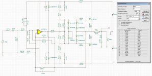
I suggest to play with A2 simulation.
I will play with A2 but I am working on AX30 layout that why I asked bimo to simulate AX30.
Attachments

Last edited:
I suggest to play with A2 simulation.
That looks promising, the only backwards is to find sutable modell for the opamp..
Sajti
I built it. Couldn't get it to work right.
Edit; I see you changed the OPS to verticals. I may try that if I can make a layout.
Edit; I see you changed the OPS to verticals. I may try that if I can make a layout.
Last edited:
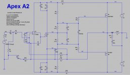
OK, I revised it.
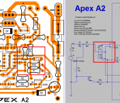
I'd like to ask, what is the purpose of BAV21 (D1) across the mirrors? Is the circuit a Blameless topology using Twin Pole compensation?
I'd like to ask, what is the purpose of BAV21 (D1) across the mirrors? Is the circuit a Blameless topology using Twin Pole compensation?
BAV21 for clamping, so there is no 'sticky' clipping. Please see Still4given measurement. In simulation, 1N4148 give slightly lower THD, but BAV21 have better harmonic profile.
This amplifier use Transitional Miller Compensation (TMC). You can read this compensation somewhere in this forum.
Q1 and Q5 should thermally couple, Q2 and Q4 too.
Q8 and Q9 is safe without heatsink, but add a small heatsink is cool 😎 😀
The bias current is about 110mA.
Part type recommendation:
C2, C6 and C7 is ceramic NP0/COG or silver mica.
C1 and C8 is MKP.
The 1/4watt and 1/2watt resistor is metal film, but choose high quality for R13 and R15.
R32 and R33 is low inductance type.
I wait the A/B result....
2SC3503 can be replace with 2SC3334 and 2SA1381 with 2SA1321. I do not have LTSpice model for 2SC3334 and 2SA1321, but I have good result using those transistor for VAS.
I built it. Couldn't get it to work right.
Edit; I see you changed the OPS to verticals. I may try that if I can make a layout.
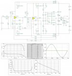
Yes, but A2 work great in this simulations.
Yes, but A2 work great in this simulations.
Yes but what good is that if it doesn't work in the real world? What opamp where you intending? Maybe TL071 doesn't match up well with your spice model.
BAV21 for clamping, so there is no 'sticky' clipping. Please see Still4given measurement. In simulation, 1N4148 give slightly lower THD, but BAV21 have better harmonic profile.
This amplifier use Transitional Miller Compensation (TMC). You can read this compensation somewhere in this forum.
The reason I asked Is because I have simulated a Blameless type circuit and I also added a BAV21 diode but placed it across the buffer and VAS trannie which was supposed to also prevent "rail sticking" at near clipping level. Your implementation looks interesting, I may have to sim it in my work 😉
Thank you Bimo.

Dear still4given,
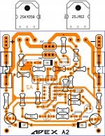
I am very much impressed with your work on PCB. It appears professional finish and more so on nice drilled holes. Is it toner transfer method and if yes and what paper do you use. How do you drill the FR4 PCB. Thanks
Katiyar
I am very much impressed with your work on PCB. It appears professional finish and more so on nice drilled holes. Is it toner transfer method and if yes and what paper do you use. How do you drill the FR4 PCB. Thanks
Katiyar
Dear still4given,
I am very much impressed with your work on PCB. It appears professional finish and more so on nice drilled holes. Is it toner transfer method and if yes and what paper do you use. How do you drill the FR4 PCB. Thanks
Katiyar
It is toner transfer. I use shelving contact paper for the medium. I described it earlier in the thread. For drills I use carbide PCB bits.
To use them you must use a high speed drill press. I use a dremel tool in a dremel drill press fixtuure. The bits are very sharp but brittle. Almost impossible to use in a hand held drill without breaking them. Using the drill press they drill like butter. One of these days I hope to have my son help me make a video of the whole process. I have borrowed tricks from several kind folks but I am pretty happy with it now and can literally make a pair of boards in less than an hour.
Hi guys,
I etched a new pair of boards today for the A2 using the OPS2134 for the IC and Laterals for the outputs. I'm having issues with a huge offset so I'm thinking I did something wrong with the layout but I have been pouring over it all day but just can't find it. Hopefully one of you eagle eyes can look it over and see where the error is.
Thanks, Terry
Attachments
Hi guys,
I etched a new pair of boards today for the A2 using the OPS2134 for the IC and Laterals for the outputs. I'm having issues with a huge offset so I'm thinking I did something wrong with the layout but I have been pouring over it all day but just can't find it. Hopefully one of you eagle eyes can look it over and see where the error is.
Thanks, Terry
Hello Terry,
which schematic are u using? I was looking at one given by apex in #5721, which I hope is "New and Improved".
reg
Hi Terry,
This might sound silly but have you made sure you are using a 'floating' power supply? This is where the transformer centre tap / filter capacitor union are NOT connected to ground but rather connect to the speaker positive. This is a 'grounded output' type topology so the PSU basically swings around the amplifier output stage, for a lack of better way to describe it. Your A2 output connection actually is a point that gets grounded.
Seems counter intuitive and a little odd but it works, plus you don't need insulators on the output devices.
Last edited:
Hi Terry,
This might sound silly but have you made sure you are using a 'floating' power supply? This is where the transformer centre tap / filter capacitor union are NOT connected to ground but rather connect to the speaker positive. This is a 'grounded output' type topology so the PSU basically swings around the amplifier output stage, for a lack of better way to describe it. Your A2 output connection actually is a point that gets grounded.
Seems counter intuitive and a little odd but it works, plus you don't need insulators on the output devices.
AX2 use grounded output topology not A2.
Hello still4given!
I have not watched any but C3 should not be connected with R2.
Regard's!
It is not wrong, C3 and R2 is in series connection order is not mater.
- Home
- Amplifiers
- Solid State
- 100W Ultimate Fidelity Amplifier