@ apexaudio: can you tell me for what the choke in the a23 in the linked youtube is used for? feedback stability?
regards
regards

@ apexaudio: can you tell me for what the choke in the a23 in the linked youtube is used for? feedback stability?
regards
Stability with capacitive load.
Regards
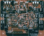

c6 seems contradicting on pcb layout of A14 and A16
C6 for bootstrap the input, the result impedance input is high.
My modification did not use bootstrap the input. Impedance input about 22K ohm is enough for me.
My PCB layout (AX16Mod) edited and produced by friend of mine.
Nice PCB
Is?Is someone who work drawing a pcb for this new schematic?
My PCB layout (AX16Mod) edited and produced by friend of mine.
Hi
Can someone share the circuit for these amplifier. The one posted next to BIMO's post does not match the components (parts) location(s).
Ready to make the PC boards based on these layout.
Terry you didn't posted listening impression after a couple days burn in.. (I would like to build one amp from Apex..)
If you burn in your amp at least 30 hours or so please share with us
Thanks
Greetings
It sounds just like the original AX14. You can't go wrong with any Mile's amps.
Thanks Terry
I never built any amp from Mile's, AX14 unknown to me.
These will be the first one 😀
Compare to PCB or LazyCat's mosfet amp? I know you built one of that..
Greetings
Usually I design an amplifier with more than 1V peak/1V/uS slew rate. It mean, with +-35VDC PSU, it must have more than 35V/uS slew rate. The requirement of the minimum slew rate to get an amplifier have sound 'airy'.
By using TMC compensation, it can have high open loop gain at high frequency. Then, it can have lower THD at high frequency. You can always hear more detail at high frequency.
Previously, I have designed typical Blameless topology with TMC compensation. According to my friend who compare my amplifier with chip amp (LM1875 and LM3886), my amplifier is better at high frequency.
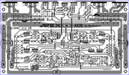
Finished layout for AX30 need some revisionof layout to find mistake.
Nice work... all MJE340 and MJE350 need heatsinks.
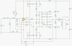
Schematic looks to have something wrong
I was curious simulating it and could not.
Despite i do not like FETs, i do think this circuit is really simple but
i could not see the mistake made.
Simulator presented error.
regards,
Carlos
I was curious simulating it and could not.
Despite i do not like FETs, i do think this circuit is really simple but
i could not see the mistake made.
Simulator presented error.
regards,
Carlos
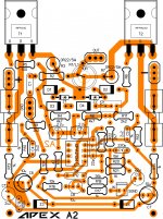
I tried to do a layout for the FET A2. If one or more of you kind folk would look it over and let me know if you see any errors I would appreciate it.
Blessings, Terry
D3 and D4 should be in contact with heatsink.
- Home
- Amplifiers
- Solid State
- 100W Ultimate Fidelity Amplifier