I have the NJWs too. I can just as easily use those.
that will work better 🙂
Regards
Juan
Actually, I was thinking about cutting off the end of the board when using the plastic outputs. I may give some TO-3 devices a try as well. Not too many parts to build a few of these. How critical are the drivers? Have other models been tried?
Thanks
Thanks
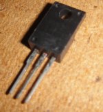
Is the first time I try AX-14 Terry and I'm really happy with the results, about the drivers I think I have seen guys using different drivers transistors, I myself decide to use the ones that are in the schematic and the good thing is that they are all plastic so one less worried about insulation just a bit of thermal paste and good to go, but I guess other driver can be use I think I have seen here is a post about driver transistors the "best ones" about cutting just try not to cut the BD139 traces 🙂 take your time
yes me too I want to try TO-3 devices too that will be next 😀
Regards
Juan
yes me too I want to try TO-3 devices too that will be next 😀
Regards
Juan
Attachments
can any one help me in ax-11 dc offset is high
did you use a coil and a 10R ? mine was unstable I notice it was getting hot, after I place the L1 20 turns of 18AWG wire +10R all went to normal that is what I did maybe you case is different I just want it to mention that 🙂
Regards
Juan
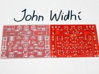
I Got my boards today from the board house. I'm trying to populate one from my parts drawers and I came across C3 at 1n5. I don't have anything close to that. I go from .22n too 450p. Can I substitute something there just so I can test it?
Thanks, Terry
Thanks, Terry
I Got my boards today from the board house. I'm trying to populate one from my parts drawers and I came across C3 at 1n5. I don't have anything close to that. I go from .22n too 450p. Can I substitute something there just so I can test it?
Thanks, Terry
do you have at least 1nF maybe you can put some in parallel under the board I mean that will give about 2nF, in my boards I have 1.5nF 100V,
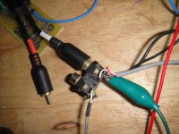
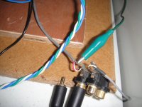
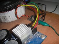
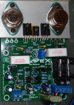
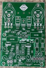
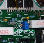
I forgot to tell you to initiate the board I read here that C7 that is in parallel with the NFB R11 22K need to be 330pF for test then after is stable and bias set then you can changed it to 47pF as I did the bias I decide to go to what is recommended so I adjusted to 15mV reading from R24 0.33 my power supply delivers 53V DC so is just right 🙂 let me know how it goes also don't forget a GND wire from the power supply 0V to the RCA GND connection see images
the last image is to let you know to insulate the top of the PCB if you are going to use " L" adapter
Regards
Juan
Attachments
Last edited:
I Got my boards today from the board house. I'm trying to populate one from my parts drawers and I came across C3 at 1n5. I don't have anything close to that. I go from .22n too 450p. Can I substitute something there just so I can test it?
Thanks, Terry
Hi Terry, any combination that will sum up close to 1500p, being put in parallel. Like 1n + 470p, 3 x 470p, etc. will be fine for testing.
Thanks guys. I used three 470p in parallel. This is the first time I have seen 1n5. I'll have to order some. Another mystery amp. One channel works and one has issues. Always a chance to trouble shoot. 🙂
Hi John'
I can take some pictures when I get home from Church today. I built the first one with TO-3 transistors for the fun of it. I have a bad offset on one channel. I have to track it down. I didn't listen to music yet but the scope looks very good on the channel that is working..
Blessings, Terry
I can take some pictures when I get home from Church today. I built the first one with TO-3 transistors for the fun of it. I have a bad offset on one channel. I have to track it down. I didn't listen to music yet but the scope looks very good on the channel that is working..
Blessings, Terry
Hi Terry,
Can we see your board 🙂
I think I will made AX-14 again with my new boards 😎
yeah man you should try out AX-14 it sound amazing good respond to tight bass and vocals are nice I love it 😀 I have a power supply board almost ready, up to 44000uF with many size option caps 🙂 next project
Regards
Juan
Attachments
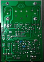
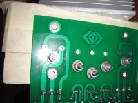
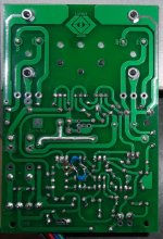
I had a few minutes before church so I took some pics. I'll show working channel on the left and troubled channel on the right. Maybe one of you eagle eyes can spot the trouble.
Thanks, Terry
EDIT; FIY I have about three volts shy of negative rails on the collector of Q9. Should be about -1.2v
Thanks, Terry
EDIT; FIY I have about three volts shy of negative rails on the collector of Q9. Should be about -1.2v
Attachments

Last edited:
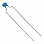
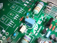
that small blue package looks like a high K ceramic.Terry this is the part number 490-7574-1-ND for the 1.5nF 100V they are really small 😀
Juan
It is too small to be a C0G/NP0
I don't recommend a HiK for coupling duty and absolutely against it for filtering duty.
I will order some film caps. I just used what I had in the drawer.that small blue package looks like a high K ceramic.
It is too small to be a C0G/NP0
I don't recommend a HiK for coupling duty and absolutely against it for filtering duty.
I had a few minutes before church so I took some pics. I'll working channel and troubled channel. Maybe one of you eagle eyes can spot the trouble.
Thanks, Terry
EDIT; FIY I have about three volts shy of negative rails on the collector of Q9. Should be about -1.2v
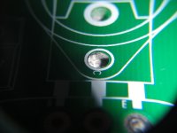
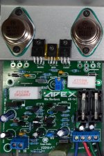
Terry look great 😀 hey I have problems the first time I put it together because some how the holes for the TO-3 has some solder residue and it was touching the heat sink, so what I did I insulated "temporary" the top of the PCB and problem went away, also you can use a large drill bit and scrape of some material to avoid that contact with the heat sink I did a quick "ghetto" fix with tape 😛
also move the pot to the middle like I have on my boards and also you cab place the jumper for the negative rail I just did to reinforce the connection for the TO-3
Attachments
-
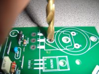 remove some material to avoid solder to touch the heat sing 2.jpg380.7 KB · Views: 286
 -
 remove some material to avoid solder to touch the heat sing 1.jpg350.9 KB · Views: 247
 -
 move the pot an solder it in the middle.jpg440.5 KB · Views: 248
 -
 bad channel top move this to the middle.jpg154 KB · Views: 269
 -
 getto tape.jpg885.2 KB · Views: 250
that small blue package looks like a high K ceramic.
It is too small to be a C0G/NP0
I don't recommend a HiK for coupling duty and absolutely against it for filtering duty.
What would be the recommended type one ?
I had a few minutes before church so I took some pics. I'll show working channel on the left and troubled channel on the right. Maybe one of you eagle eyes can spot the trouble.
Thanks, Terry
EDIT; FIY I have about three volts shy of negative rails on the collector of Q9. Should be about -1.2v
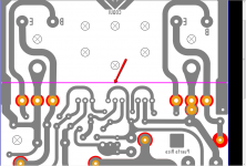
I think there is mistake marked on picture.
Attachments
- Home
- Amplifiers
- Solid State
- 100W Ultimate Fidelity Amplifier