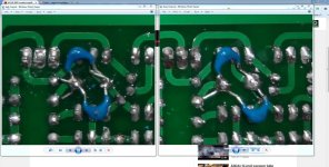
I think there is mistake marked on picture.
wow! I didn't even see that 😱 the leads of the cap was jumped the other trace good eye man 😀
Regards
Juan
I checked that after I posted the picture no short there. That is on the working channel anyway.
I know it looks bad in the picture but the lead was not touching. I shouldn't have left them long but I plan to replace them when I get the right cap so I left the leads on so I could reused them later. Anyway, They were not touching. I went ahead and trimmed the leads but the issue remains. I just got home so I will have time now to sit and write down all my voltages on a schematic and hopefully make sense of what is going on. If I still haven't solved it I will post the schematic for further review.
Thanks, Terry
Thanks, Terry
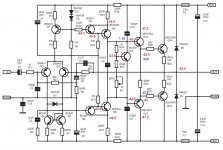
OK I have been over and over the board. I just can't seem to find where the negative voltage is coming from. I am attaching a schematic hoping that an answer is apparent to one of you.
Troubled board voltages are in red
Working board voltages are in blue
Here is what I have tried so far.
Replaced Q8 no change
Replaced Q9 twice. No change
Replaced Q10. No change
Replaced Q11, Q13. No change.
Here are a few things I noticed
vbe for all transistors is between .558V and .630V
The bias adjustment behaves normally on the troubled board
All voltages match between the two boards from Q1-Q7 except for the bases of Q1&Q2. Those are within a few mV. Obviously there is a large drop across R11 on the troubled board.
Thanks, Terry
Attachments
Last edited:
Hi Terry,
Try to replace Q1 & Q2 with matched hFE if you can 🙂
(or swap their position)
I will try for my build, I will post some picture too 😀
Try to replace Q1 & Q2 with matched hFE if you can 🙂
(or swap their position)
I will try for my build, I will post some picture too 😀
I matched them. Even if not it's hard to believe they could cause -42V offset. Thanks for looking.
Yes it sort of looks that way but have gone over the board several times looking for shorts. I have not been able to find any. I will check some more tomorry.
Thanks' Terry
Thanks' Terry
I hope you guys are remembering to ground the input ground to the star ground, this connection is usually included most pcb design on other amplifiers, but in the original version of the AX14 APEX decided to run it as a discrete wire.
Maybe replace C13 with a 10R resistor, for initial testing, that should connect input ground to main ground on the pcb itself.
Regards
Maybe replace C13 with a 10R resistor, for initial testing, that should connect input ground to main ground on the pcb itself.
Regards
Is it a coupling cap, or a filtering cap?What would be the recommended type one ?
Yes it sort of looks that way but have gone over the board several times looking for shorts. I have not been able to find any. I will check some more tomorry.
Thanks' Terry
Power off, measure resistance Q8 c/e. If shorted, pull Q8 out, measure again. If still shorted it is probably solder drop or something.
Those transistors you replaced, are they ok?
Last edited:
An externally hosted image should be here but it was not working when we last tested it.
So I build my own too 🙂
I will check the voltage & I hope nothing bad happen
note that I use KSC2690A & KSA1220A for Q8 & Q9
because so many fake MJE ini my local suplier 😀
Last edited:
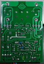
I found it. Thanks for everyone's help. AndrewT got me looking at Q2 again and I finally saw it. I don't know how I missed it but the 22K NFB resistor was not soldered at one end. A touch of solder and everything is beautiful. Finally I can play some music through it and do some comparisons. I'll let you know how it sounds very soon.
Blessings, Terry
Blessings, Terry
Attachments
It's alive! Playing music. Just through my test speakers so far but sounds very nice. Dead quiet and .001mv offset on both channels. Pretty impressive so far. I have a question about bias. I didn't have any 0R33 resistors so I used 0R68. If I had read more of the thread I would have seen the some guys used 0R22. I have plenty of those so if necessary I can change them. Anyway, with the 0R68 I have it set at 48mv across a single resistor. Is this in the ball park? Any issues with using 0R68 for the emitters?
Here's a pic of it playing on +-47V rails.
Blessings, Terry
Here's a pic of it playing on +-47V rails.
Blessings, Terry
Attachments

Terry, if you place two 0R68 resistors in parallel, it will be very close to the desired value (0R33). Sorry, maybe you know that...
really nice Terry 😀 I'm glad you found out the little problem, hey about bias I set my boards to 15mV across reading from the 0.33 5W if you are going to use 0.22 it be like 10mV +/- setting up, giving about 45mA I means depends how you want it, some people like it to run a bit hotter or colder, so maybe yeah 45mA to 50mA
hey quick question Terry the mounting of the TO-3 was aligning pretty well ?
Regards
Juan
hey quick question Terry the mounting of the TO-3 was aligning pretty well ?
Regards
Juan
Terry, if you place two 0R68 resistors in parallel, it will be very close to the desired value (0R33). Sorry, maybe you know that...
Yes I know. I have some 0R33 coming. The 0R68 seem to be working fine so I'll probably just leave those for now. I plan to build a couple more different versions since I have plenty of boards. I want to try one with NJW3281/1302 outputs. I'm also going to try using just the IPS section for a Slewmaster. Should be interesting. I might even try throwing some MOSFETs on the backend. Fun Stuff!
Hi Juan,
The TO-3s fit fine. No problems.
- Home
- Amplifiers
- Solid State
- 100W Ultimate Fidelity Amplifier