Those Sankens you mention look incredible from the datasheet. If they are a little slower than the 1837/4793, they will still have a linear gain region 10 times larger and a larger SOA. I really want to try some of those, it would be nice to do a group buy from Ten Four LTD.
The MJE parts may be comparable but they will be much slower, with much higher capacitance. The 4883/1859 would be very difficult to substitute.
Speaking of which, here are some SPICE models I created for them. I can't say how accurate they really are because I guess on a lot of parameters. But I think Cje and Cjc are accurate as I used them to fit Ft data. Hfe is an approximation as the model seems incapable of producing the curves on the datasheet - whether this is the fault of the datasheet or the model I do not know. I am hoping that my VAF estimates are very pessimistic.
.MODEL 2SC4883A_k npn (IS=725f BF=114 NF=1
+ VAF=40 IKF=2.25 ISE=7e-11 NE=10 BR=1.97064 NR=1.50008
+ VAR=22.902 IKR=35.9467 ISC=4.75e-12 NC=3.59375 RB=7.5 IRB=0.1
+ RBM=0.1 RE=0.0001 RC=0.130733 XTB=0.337319 XTI=1.40625
+ EG=1.31 CJE=1n VJE=0.651779 MJE=0.35303
+ TF=1.2n XTF=1.35721 VTF=0.995654 ITF=1 CJC=90p
+ VJC=0.429208 MJC=0.35114 XCJC=0.803125 FC=0.533449 CJS=0
+ VJS=0.75 MJS=0.5 TR=85n PTF=0 KF=0 AF=1)
.MODEL 2SA1859A_k pnp (IS=600f BF=148 NF=1
+ VAF=30 IKF=6 ISE=4.79702e-14 NE=4 BR=1.96197 NR=1.29503
+ VAR=23.2874 IKR=9.99625 ISC=4.79702e-14 NC=3.59375 RB=6.5
+ IRB=0.108633 RBM=0.101928 RE=0.000100027 RC=0.122304
+ XTB=0.137608 XTI=1.0316 EG=1.32 CJE=1.495n VJE=0.651747
+ MJE=0.353069 TF=1.7n XTF=1.35721 VTF=0.99569 ITF=0.999994
+ CJC=68p VJC=0.42654 MJC=0.24282 XCJC=0.803125 FC=0.533457
+ CJS=0 VJS=0.75 MJS=0.5 TR=188.8n PTF=0 KF=0 AF=1)
- keantoken
Last edited:
Good to know that those sanken parts should be ok. I've had a slight redesign of the PCB so that it matches the schematic for the AX-20 protection circuit. I've also noticed that there is a PA protection circuit called the H900 that may also be used. There are too many options and i lack the knowledge/experience to know which is best.
anyway this is how the pcb design looks now. (should be an exact match for the schematic now)
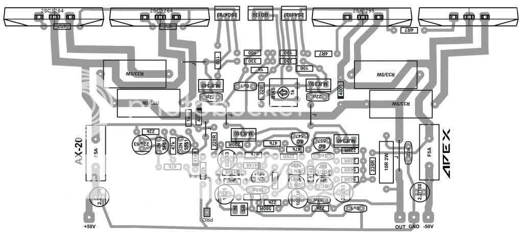
anyway this is how the pcb design looks now. (should be an exact match for the schematic now)
With +/-50V you can use: MJE15030/MJE15031; MJE15032/MJE15033; 2SC2073/2SA940 I had use 2SC2073/2SA940 and it works perfect.
Regards
Regards
If i incorporate the changes you've made to that AX14 design into the AX20 will that negate the need for the extra protection board like the H900/PSU-7?
Been looking at suitable transformers today, what would the maximum input voltage be for the AX20? I've been looking at 50-60Vx2, 500-1000VA transformers. (or potentially running a 25-30V transformer with the outputs in series to double the voltage.) Would it be better to use the 50-60V transformer and have 2 separate rectifying/filtration boards or a single board using the series wiring of the secondary windings? (I reckon the separated supplies myself just want to be sure)
Been looking at suitable transformers today, what would the maximum input voltage be for the AX20? I've been looking at 50-60Vx2, 500-1000VA transformers. (or potentially running a 25-30V transformer with the outputs in series to double the voltage.) Would it be better to use the 50-60V transformer and have 2 separate rectifying/filtration boards or a single board using the series wiring of the secondary windings? (I reckon the separated supplies myself just want to be sure)
If i incorporate the changes you've made to that AX14 design into the AX20 will that negate the need for the extra protection board like the H900/PSU-7?
Been looking at suitable transformers today, what would the maximum input voltage be for the AX20? I've been looking at 50-60Vx2, 500-1000VA transformers. (or potentially running a 25-30V transformer with the outputs in series to double the voltage.) Would it be better to use the 50-60V transformer and have 2 separate rectifying/filtration boards or a single board using the series wiring of the secondary windings? (I reckon the separated supplies myself just want to be sure)
If you incorporate the changes into AX20 PSU (+/-60V) is only that you need.
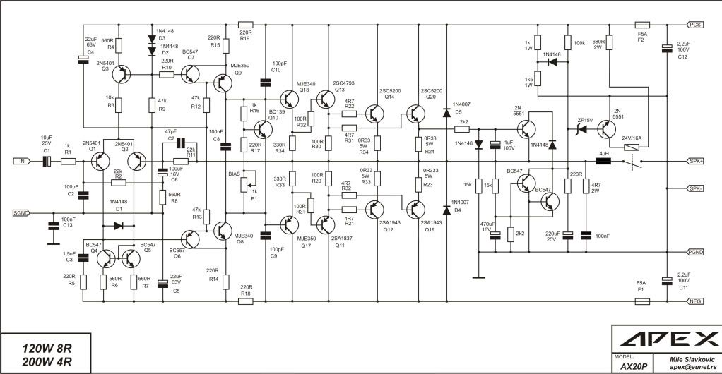
OK, greatly appreciate the guidance here. This is how the schematic has come out.
I've got so far with a rough construction of the pcb but got lost at the relay. I've circled the two bits that have got me slightly lost.
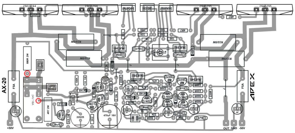
I've got so far with a rough construction of the pcb but got lost at the relay. I've circled the two bits that have got me slightly lost.
Oh! That would be great!!!😛Schematic of AX20P is OK, but you have lot of work on pcb, maybie 'alex mm' can help you 🙂
Yes I think a more experienced PCB designer is needed here. I've got the AX20P schematic drawn up in Livewire and the basic version without protection drawn up in ExpressSCH if it helps.
To Mile
Can i use 2n3773 for the output stage(quasi-complementary) for this ax-14 amp
then voltage will be limited to how many volts for two pairs??
Can i use 2n3773 for the output stage(quasi-complementary) for this ax-14 amp
then voltage will be limited to how many volts for two pairs??
Can i use 2n3773 for the output stage(quasi-complementary) for this ax-14 amp
then voltage will be limited to how many volts for two pairs??
Can i use 2n3773 for the output stage(quasi-complementary) for this ax-14 amp
Can i use 2n3773 for the output stage(quasi-complementary) for this ax-14 amp
I suggest http://www.diyaudio.com/forums/solid-state/167394-quasi-amplifier-beginners-56.html for 2N3773
![SDC10507 [1024x768].JPG](/community/data/attachments/245/245224-caf1fd64a85b19d305472446a2fb209e.jpg?hash=yvH9ZKhbGd)
![SDC10508 [1024x768].JPG](/community/data/attachments/245/245233-4b9657bba25ac50d3eaee8729e66e72b.jpg?hash=S5ZXu6JaxQ)
![SDC10509 [1024x768].JPG](/community/data/attachments/245/245239-c1b0c257a833e12b5c0a8e74cf28e474.jpg?hash=wbDCV6gz4S)
Also AX-14 with 2 pair of output transistors. Can I use this on 80w/4ohm speaker, for PA or I need to add more outputs? It is working on +/-35V DC and bias is 60mA.
Attachments
![SDC10502 [1024x768].JPG](/community/data/attachments/245/245246-ec5fc2585d3868d48a24ca48cc5ee5f0.jpg?hash=7F_CWF04aN)
![SDC10503 [1024x768].JPG](/community/data/attachments/245/245254-77d85e6f5f10a35be50a7eadb2370802.jpg?hash=d9heb18Qo1)
![SDC10504 [1024x768].JPG](/community/data/attachments/245/245262-a3e154c30ed09583814a7cfc220016c1.jpg?hash=o-FUww7QlY)
Also AX-14 with 2 pair of output transistors. Can I use this on 80w/4ohm speaker, for PA or I need to add more outputs? It is working on +/-35V DC and bias is 60mA.
AX14 working on +/-35V can be use with 4 ohm speaker with single pair of output transistors, with 2 pair can be use on 2 ohm speaker but need fan cooling.
What would be benefit of using two pair of output transistors (mjl21193/21194) and +/-50VDC supply? No doubt in sound quality,what power could be reached with 4 and 8 Ohm load?
Last edited:
- Home
- Amplifiers
- Solid State
- 100W Ultimate Fidelity Amplifier